Frequently Asked Questions (FAQs)
Questions about our Products? Get your answer.
Service
Please note our General Terms and Conditions, which can also be found on our homepage. KNAUER does not cover shipping costs for standard or warranty repairs.
If you feel you need a service technician on site, please contact your contact your local distributor. We will be happy to review the problem with you and provide assistance. Sometimes a problem can be solved without a service technician, for example with a remote session. If the problem does require an on-site visit, we will arrange this for you.
KNAUER support can provide on-site assistance via remote PC control. To ensure quick assistance, make sure you have a stable Internet connection from the PC you will be controlling the instrument from. Connect the instrument to the PC. Let us know when it would be best for you to have a Team Viewer session.
In Germany: If we contact you to offer on-site service, we will inform you of the first available date. In most cases, however, KNAUER is able to help you remotely, so don't hesitate to contact us!
Worldwide: Please contact your local distributor.
All KNAUER instruments are warranted for 2 years unless otherwise stated. The warranty period begins upon receipt of the product or, if ordered, upon commissioning. In case of delayed commissioning, the warranty period begins no later than four weeks after receipt of the goods, unless the supplier is responsible for the delayed commissioning.
Repairs offered by KNAUER usually take no more than 7 business days after confirmation of the cost estimate. An estimate of the total time it will take to return your instrument to KNAUER depends heavily on the type of instrument, the severity of the failure, and related shipping factors. As soon as the instrument arrives at KNAUER, you will receive a delivery confirmation from our repair team. If you would like to be kept informed about the progress of your repair, you can contact KNAUER Customer Service at any time (support@knauer.net).
In order to determine the cost of repair, KNAUER must first perform a failure analysis to determine how much time and spare parts will be required. This means that we can only provide you with a cost estimate after the instrument has been sent to KNAUER, not before. If you do not agree with the estimate, you can always decline the repair and return the instrument. In this case, the unit will be returned to you and you will be charged one hour for the failure analysis. There is no charge for a warranty claim. For more information, please see our terms and conditions.
KNAUER is committed to environmental protection. Therefore, we encourage you to download our user manuals online. They are always up to date. You can find them here.
Yes, KNAUER offers regular software trainings. For quick help, we also recommend our video tutorials.
If you have an affected instrument, please first contact KNAUER Customer Support (support@knauer.net). We will analyze your request and, if necessary, provide you with an RMA number so that you can send the instrument to us for repair. Please include the serial number of the instrument and a short description of the problem in your first email. You can always find it on the back of the unit.
KNAUER Customer Support offers you the possibility to check your local system via Team Viewer. This software allows us to remotely control your PC and analyze the problem you are experiencing. Please download the TeamViewer program from our website. Make sure you have a stable Internet connection from the PC you will be controlling the device from. Connect the device to the PC and let us know when it would be best for you to have a TeamViewer session.
If you are not sure whether your instrument can be serviced or repaired, do not hesitate to contact KNAUER Customer Support (support@knauer.net) and provide us with the serial number of the instrument, a description of the failure, and if possible, a photo of the affected instrument and/or part. We will then provide you with a support ticket number and analyze whether we can help you with your request.
If you receive a KNAUER product and notice a defect, please contact KNAUER Customer Support (support@knauer.net) immediately with a description of the defect, your order details, and photos of the affected part and its packaging. Please note that you must immediately inspect the delivered goods and report any defects in writing to KNAUER Customer Service within 10 working days of delivery.
Once you have contacted KNAUER Customer Service and we have confirmed that your instrument is eligible for repair, you will receive a Return Material Authorization (RMA) number. Please fill out the service request form, pack it together with the instrument and send it to KNAUER. The address is already included in the document.
KNAUER customer support by phone and e-mail is always free of charge.
Please contact KNAUER Customer Service. We will confirm whether the instrument is eligible for repair and provide you with an RMA number for return shipment. Please fill out the service request form, pack it together with the instrument and send it to KNAUER. The address is already included in the document.
You will usually receive a response within 24 hours (business days) - often the same day. We do not use automatic confirmation emails because we want to give you helpful feedback with our first response. If you do not receive a response within 48 hours (business days), please contact us again as a precaution. Thank you very much.
Depending on the circumstances, we will evaluate the cost of on-site service. This can vary greatly depending on distance, parts, labor, and warranty.
Assistant Combination Modules
Configuration
An assistant with the following configuration is not allowed:
1. more than two pump modules - high pressure gradient is not supported
2. more than one UV detector
3. without a plug-in module
Pumps
We offer 15 different pumps with 10 or 50 ml pump heads and with or without pressure sensor. The materials used are stainless steel, ceramic or Hastelloy C (only for pumps without pressure sensor).
Valve drive
The universal valve drive identifies valves using RFID technology and allows GLP data to be read. All V 4.1 valves are supported, regardless of number of ports and position.
UV detectors
The compact single wavelength UV detector is available in basic and fiber optic versions. The wavelength is adjustable between 190 - 500 nm.
This question applies to the now discontinued ASM 2.1L version of the LC Module Docking Station. Learn more about the new and improved ASM 2.2L version here.
The maximum number of modules of the same type in the ASM 2.1L version of the LC module docking station is:
- 1x degasser (an assistant with only one degasser is not allowed)
- 1x detector
- 2x AWB02 valve drives
- 2x pumps (only with ClarityChrom or PurityChrom software)
- HPG (High Pressure Gradient) not supported
- A maximum of two pumps are allowed in each assistant. HPG (High Pressure Gradient) is not supported.
- A maximum of one detector is supported in each assistant.
- A P 4.1S pump cannot be placed to the right of a UVD 2.1S detector.
- A detector between two pumps is not allowed.
- A maximum of two AWB02 VICI valve drives are supported in each assistant.
- A maximum of one degasser is supported in each assistant.
- An assistant with only one degasser is not allowed.
The Assistant ASM 2.1L is a compact combination module that can be equipped with up to three instrument modules. Valves, pumps, degassers and UV detectors are available for selection.
IP Port Connection

If the assistant contains only one module, it is always connected to the left port (IP port 10002), regardless of the module position. The assistant module itself is addressed by IP port 10001. Addressing modules by IP port is required for PurityChrom® software and single instrument configuration.
For two modules in the assistant, IP port 10003 is not connected. The module in the middle position is connected to either 10002 or 10004, depending on the position of the second module. The assistant module itself is addressed by IP port 10001. Addressing modules by IP port is required for PurityChrom® software and single instrument configuration.

For three modules in the assistant, the left module is connected to IP port 10002, the middle module is connected to IP port 10003, and the right module is connected to IP port 10004. The assistant module itself is addressed by IP port 10001. Addressing modules by IP port is required for PurityChrom® software and single instrument configuration.

Service
The lamp of the ASM 2.2L UV detector plug-in module UVD 2.1S can be easily replaced.
- Remove the UV detector module from the assistant
- Remove the cover of the plug-in module
- Replace the lamp
- Replace housing cover
- Insert the plug-in module into the assistant
The lamp of a UVD 2.1S UV detector built into an assistant can be easily replaced. Please refer to the Lamp Replacement Supplement (V6817).
Software Functions
When modules are addressed by software as an Assistant Configuration, the following functions are supported. An injection module is a combination of a pump and a 6-port, 2-position valve.


A) Assistant Configuration: The ASM 2.1L is supported as a complete device. Modules are addressed through the assistant.

An injection module is a combination of a pump and a 6-port, 2-position valve.
B) Single device configuration: The ASM 2.1L is not supported as a single device. Integrated modules are addressed as separate devices through the IP port.

An injection module is a combination of a pump and a 6-port, 2-position valve. In a single device configuration, the modules are addressed through IP ports.
Detectors
The KNAUER flow cell cartridges (e.g. LightGuide AMC19XA, AMD59XA and PressureProof AMC38, AMB18 flow cells) for the AZURA® DAD 6.1L, DAD 2.1L and MWD 2.1L detectors should be handled carefully to ensure optimal performance. An important aspect of handling your flow cell cartridge is that you should not touch the fiber optic ends with your fingers. Your fingers can leave a thin layer of grease on the fiber ends, which can drastically affect the performance of the flow cell and detectors. To diagnose this problem, we recommend that you generate an intensity spectrum (via your chromatography software under Diagnostics). Dirty fiber ends result in little or no UV light (see below). To restore performance, simply clean the fiber ends with alcohol and a cotton swab.

Cartridge Flow Cells - Diagnostics
Certain buffers and organic solvents interfere with UV detection. A mobile phase with a UV cutoff below the detection wavelength will not interfere with signal sensitivity. Examples of UV cutoffs: water 185 nm, methanol 205 nm, acetonitrile 190 nm. A suitable wavelength for an acetonitrile/water mobile phase must be higher than 190 nm.
For best results and to avoid peak broadening, it is recommended to use the lowest dead volume combination of flow cell and column. KNAUER offers analytical and preparative flow cells. UHPLC flow cells with 2 µl (10 mm), analytical flow cells with either 10 µl (10 mm) or 2 µl (3 mm). Preparative flow cells are available with 1.7 µl or 3 µl (0.5 mm). The flow cell with the shorter path and smaller cell volume will produce sharp peaks due to minimized dead volume. Using a flow cell with a greater path length will make your detection more sensitive. The correct flow rate depends on the column dimensions and the application. The lower the flow rate, the greater the influence of dead volume. The following flow rates are typical guideline values for a material with a particle size of 5 µm: ID 2 mm flow 0.15 ml/min-0.5 ml/min, ID 3 mm flow 0.6 ml/min, ID 4+4.6 mm flow 0.8 ml/min-2.0 ml/min, ID 8 mm 2.0 ml/min-4.0 ml/min.
Traditional monochromator-based UV detectors record 2D data as a chromatogram. These instruments are called VWD or MWD. However, 3D-like measurements can be made by scanning the wavelength range. VWD or MWD detectors cannot record 3D data for the entire analysis time, but only in programmed time frames.
Instruments based on DAD technology can record 3D data in addition to 2D data over the entire analysis time.
3D data means that full UV spectra are measured and plotted over time. This is useful for unknown analytes or targets with different UV characteristics. In addition, 2D chromatograms can be extracted from the 3D data at any wavelength.
A refractometer is used to determine the refractive index of a medium by optical measurement. The refractive index (n) is a quantity that relates the velocity of propagation of light in a medium (cM) to the velocity of propagation of light in a vacuum or the speed of light in a vacuum (C0), which is defined as 1. Differential refractometry is a robust method that allows universal detection and has been accepted and established for many years.
Advantages: low price, easy to use, good linear behavior, universal application
Disadvantages: lower sensitivity than other universal detectors, not gradient compatible
If the error message is "No New Data from Detector" (for PurityChrom®) or "Error:235, Instrument not validated" (for ClarityChrom®), the problem is not related to communication between the instrument and the software. In these cases, the detector is not validated, which can be easily seen on the detector's status LEDs. If the middle LED is flashing, the device is being validated. Successful validation is indicated by the green center LED. If the center LED is off, the validation was not successful. There are several reasons for this:
- Lamp is off
- Lamp is too old
- Flow cell is broken or contaminated
- Air in the flow cell
- Interruption of validation due to an early software startup
To solve this problem, follow these steps:
- Check if the lamp is on. If not, turn on the lamp and restart the validation. For ClarityChrom® this can be done from the diagnostic window. For PurityChrom®, the instrument must be restarted with a power cycle. Always wait to start your software until the validation is complete.
- If the lamp is on and the validation was not successful, install the test cell (AMLX8) and restart the validation as described in 1.
- If the calibration with the test cell was successful, reinstall the flow cell and flush the flow cell for at least 10 minutes at a flow rate of at least 1 ml/min. Then repeat the calibration as described above. If validation is successful, the problem was caused by air in the flow cell. If validation is not successful, the flow cell may be dirty. In this case, clean the flow cell as described in the flow cell supplement and then repeat the validation as described above. If cleaning does not result in successful validation, record an intensity spectrum as described in the software manual. It may be necessary to replace the flow cell. Flow cells are part of a detector that ages over time and may need to be replaced after some time depending on the operating conditions.
- If validation with the flow cell was not successful and you are sure that the detector lamp is working properly, please contact KNAUER Customer Support (support@knauer.net) for further assistance.
Depending on the optical properties of the analyte, stray light correction can improve linearity by up to 25%. In some cases, overcompensation may result in peak splitting above a certain threshold. The extended linear range option can be enabled and disabled in your software under Advanced Settings.
The AZURA® DAD 6.1L's built-in Polka-Dot technology provides a seamless blend of UV light from the high brightness (and long life) deuterium lamp and VIS light from the halogen lamp. The proportion of light from each source is regulated via a polka-dot design to optimize light intensity across the entire 190-1000 nm spectrum. This provides excellent sensitivity over the entire wavelength range.
When a specific wavelength is set on a diode array detector (DAD), the total number of wavelengths actually registered by the photodiode is called the bandwidth. For example, a wavelength set at 254 nm with a bandwidth of 4 nm (254/4 nm) results in an average absorption of 252-256 nm. The choice of bandwidth is a balance between sensitivity and selectivity. Narrow bandwidths increase selectivity, while wide bandwidths increase sensitivity. The default bandwidth for the AZURA® DAD family is 8 nm and should not be confused with spectral bandwidth, which is a physical property of a given detector.
White light is a mixture of electromagnetic waves of different wavelengths. A monochromator is used to separate a single wavelength from an incoming beam of light. After passing through the entrance slit of the monochromator, the light is split into its wavelengths. This can be done by a dispersive element such as a prism or, as in KNAUER monochromators, by an optical grating that diffracts the incoming light. Another slit at the outlet of the monochromator allows only a small wavelength range of the expanded light beam to leave the monochromator and enter the flow cell. Because the outlet slit is fixed in position, it is necessary to rotate the grating in the monochromator to select the desired wavelength for HPLC analysis.

Certain substances can stain the LightGuide flow cell cartridges, resulting in a loss of transmission and performance. The LightGuide flow cells can be restored by an advanced cleaning procedure. This cleaning procedure is described in the KNAUER Flow Cell Cartridge Supplement (V6708A). Another way to clean your flow cell is to use a special cuvette cleaning concentrate (e.g. Hellmanex III from Hellma Analytics). In this case, follow the manufacturer's instructions.
To minimize baseline drift due to refractive index effects, a reference wavelength can be set to correct the baseline for the AZURA® DAD family (DAD 6.1L, DAD 2.1L and MWD 2.1L). The reference should be set in the same spectral region as the signal wavelength (UV or VIS) and at a wavelength where the analyte of interest has no absorbance. The default reference wavelength is 360/30 nm.
Deuterium lamps are a common light source for UV detectors such as variable wavelength, multiple wavelength, and diode array detectors. The performance of these lamps degrades over time. KNAUER detectors automatically compensate for the gradual loss of performance, but after 2000 hours of operation or 5 years of storage, these lamps need to be replaced.
For KNAUER detectors with fiber optic option, fiber optic cables are available in custom lengths. Lengths typically start at 400 mm and go up to 10000 mm. The length can be optimized for a specific application.
Some of the KNAUER flow cells used in our UV detectors are considered consumables. This applies to all flow cell cartridges (used in the AZURA® MWD 2.1L, AZURA® DAD 2.1L, and AZURA® DAD 6.1L) of the PressureProof type as well as the LightGuide type. These flow cells cannot be repaired by KNAUER. If there is a significant drop in performance of these flow cells, our cleaning procedures may be a solution to restore performance. These procedures are described in the Flow Cell Cartridge Supplement (V6708A).
For some of our classic flow cells used in the AZURA® UVD 2.1S, AZURA® UVD 2.1L, BlueShadow 40D and BlueShadow 50D we offer repair kits. These kits contain different lenses, light guides, gaskets or pressure nuts depending on your flow cell and can be useful if dirt has accumulated on the glass surface of the flow cell or if seals have leaked over time.
If your flow cell has a built-in heat exchanger (e.g. P/N A4061XB, A4061, A4061V2) and the heat exchanger is blocked, there is no way to repair the flow cell.
For further assistance, please contact KNAUER Customer Service at support@knauer.net.
The cartridge flow cells on the AZURA® DAD and MWD detectors are quick and easy to replace. However, sometimes the mechanism can jam. To prevent this, it is advisable to remove the capillaries before removing the flow cell.
Due to the low limits of aflatoxins in food and the low inherent fluorescence of aflatoxin B1 and G1, the aflatoxin analysis has to be optimized by derivatization.
This is done photochemically with the UVE UV-Derivatization Module under UV light radiation at 254 nm. The UVE reactor can also be used to enhance the detection of other mycotoxins such as deoxynivalenol (DON) or zearalenone (ZON), phenylurea pesticides, barbiturates, vitamin B3 and N-nitrosodiethanolamine (NDELA).
SIM
SIM stands for "selected ion monitoring" - selected ions are measured continuously. This results in high sensitivity because an ion species can be summed over the entire time window of the measurement. In SIM mode, no full mass spectrum is measured.
MIX/Interleave
Selected masses are measured continuously with high sensitivity. In addition, a mass spectrum is recorded at intervals.
Scan & XIC
XIC stands for "extracted ion chromatogram" - a complete mass spectrum is continuously recorded and the selected mass channels are extracted from it. The sensitivity for the mass channels is lower than in SIM mode, but the full spectrum provides much more information, such as peak purity.
The eluent is sprayed with nitrogen at atmospheric pressure in the presence of a strong electrostatic field. This produces charged droplets. An enveloping heated stream of nitrogen evaporates the solvent molecules. Eventually, a small droplet carries so many charges that it bursts (Coulomb explosion). This process continues faster and faster until virtually only analyte ions remain. Depending on the polarity of the voltage applied to the ion source electrodes, protonated quasi-molecular ions [M + H]⁺ or negatively charged deprotonated quasi-molecular ions [M - H]⁻ are formed. Which is preferred depends on the type of molecule.
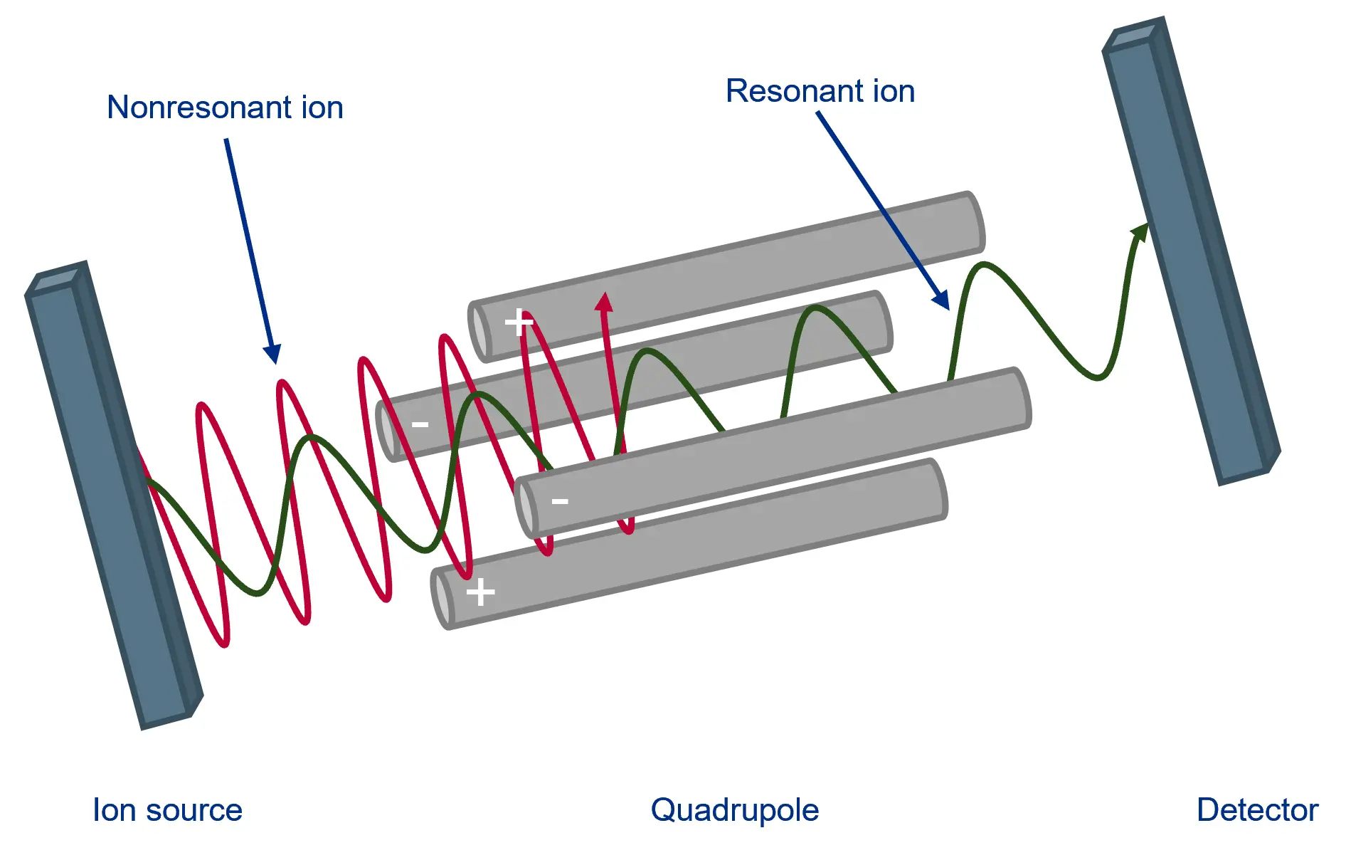
In a mass spectrometer, the analytes are separated as charged molecules (in some cases also as fragments/aggregates) in an electric field. They must be introduced in a gaseous state. The "gas" must be very highly diluted so that the ions can be analyzed on individual trajectories. Otherwise, they could collide with other ions, transferring their charge and forming hybrids or influencing each other's trajectories. Coupled to an HPLC system, the ion source must be able to separate and ionize the analytes from the large excess of eluent/solvent as effectively as possible so that the ions can be analyzed in the quadrupole.
 need an ion source?")
In a quadrupole mass spectrometer, ions produced in the ion source are accelerated by a static electric field between the ion source and the detector. The ions pass through four parallel rod electrodes that form a square (quadrupole) in the direction of ion flight. An alternating electric field is applied to the electrodes (homopolar on opposite electrodes), which can be modulated. The alternating field can be adjusted so that the ions are selected according to their mass/charge (m/z) ratio so that only ions of a defined mass can pass through the field to the detector.
For very simple separations of clearly separated peaks, some users do not need a detector. Of course, this requires high reproducibility of the separation and knowledge of the exact retention times.
Alternatively, many fractions can be collected, but they have to be analyzed for the content of the desired substance. Depending on the content, the appropriate fractions are then combined. Both approaches involve risks or require additional time.
The more complex the mixture to be purified, i.e. the higher the number of components contained, the more important it is to have fractionation based on a detector signal that covers the relevant components of the sample. The detector signal and retention time window are used to "cut" the peaks as accurately as possible. Refractive index (RI) and UV detectors are often used for this purpose.
To detect peak overlap or co-elution and to estimate peak purity, a diode array detector can record spectra for the expected peak of the target compound and perform fractionation only if it meets a predetermined specification. Although this is safer than simple UV detection, UV spectra are sometimes too similar to be clearly distinguished.
An MS detector is much more selective and can detect the signal of a specific molecular mass (selected ion monitoring, SIM) - usually the target molecule. The fraction is then collected only if the signal exceeds a predefined threshold. Because of the high specificity, the peak can be cut very precisely. The effort of downstream analysis and combination of fractions with a sufficiently high content of the target substance can be largely eliminated.
In this way, mass-triggered purification increases the robustness of the method and saves time.

Dosing Pumps
Every HPLC system is equipped with a pump for high-pressure solvent delivery. HPLC system pumps often share the same footprint as all other system components, allowing all HPLC instruments to be stacked, saving bench space. HPLC System Pumps are controlled by a chromatography data system and therefore require very few controls directly on the front panel of the instrument.
Dosing pumps are optimized to be stand-alone devices. They are very compact and have a control panel for direct control of all functions such as purging, flow rate adjustment and gradient composition. In addition, KNAUER BlueShadow dosing pumps feature a wake-up control for automatic solvent delivery at a predefined date and time and other advanced programming options.
The BlueShadow pumps 40P and 80P as well as the AZURA P 2.1S and P 4.1S are available as stand-alone units. The AZURA P2.1L and 6.1L are designed as system units, so they don't have their own display. Their footprint and design fits perfectly into our AZURA systems.
Use the following chart to find the pump head material best suited for your application:
Stainless Steel (1.4404/316L) | Ceramic (Al2O3) | Titanium (TiAl6V4) | Hastelloy C-276 | |
Application Requirements | Standard material in HPLC | Corrosion resistant, biocompatible | Biocompatible | Corrosion resistant |
Compatible Liquids | Organic solvents, oils, water, diluted acids | Organic solvents, buffers, salt solutions, water, acids, bases | Buffers, non-oxidizing organic solvents, water | Oxidizing, reducing and mixed solvents, concentrated acids |
In- and Outlet Connections | Stainless steel | PEEK | Titanium | Hastelloy C |
For further questions about chemical compatibility, contact support@knauer.net.
By changing the pump head, the user can easily adapt the pump to a different flow and pressure range. Analytical pumps can be operated up to 50 ml/min and preparative pumps up to 1000 ml/min.
Please refer to the flow/pressure diagrams for BlueShadow 40/80P and AZURA P2.1S/P41S pumps for details.


Connect in the following order:
- An analog cable from the mini Cori-Flow to the pump.
- A tube from the pump to the Cori-Flow (an adapter may be necessary).
- The Cori-Flow via RS-232 cable to the PC.
- Then start the PC and the following software packages from Bronkhorst: FlowDDE (wait until there is a connection) or FlowPlot

The mini CORI-FLOW instruments are shipped with an installation CD containing three applications: FlowDDE, FlowPlot and FlowView. FlowDDE is a server application for data exchange between the instrument and Windows applications. FlowPlot and/or FlowView can be used to monitor the instrument. FlowPlot must be used for data recording, instrument setup, and flow control.

The following video tutorials from the original manufacturer show the installation and basic use of FlowDDE and FlowPlot:
For continuous operation, we recommend a flow rate of approximately 40% of the maximum flow rate.

Our pump heads are made of materials resistant to common HPLC solvents. All pumps can be used under standard conditions (1 < pH < 13, no oxidative or reductive reagents).
If you are using buffers or other highly concentrated salt solutions, you should use ceramic or titanium pump heads. For liquids with pH < 1 you can use the Hastelloy version of the 10 or 50 ml pump head.

If your eluent is more aggressive (oxidative/reductive or a pH > 13), you will need to use the Kel-F / FFKM upgrade kits:
Depending on your needs, we offer different types of pumps:

If your HPLC or FPLC system is unable to achieve the specified flow rate, the system pump needs to be serviced. In many cases, a faulty check valve is the cause. Trained personnel with access to the KNAUER ServiceTool can record the pressure profile of the pump for diagnostic purposes. In most cases, a check valve malfunction can be easily detected.
The figure shows the pressure profile of an intact pump head (left) and a pump head with defective check valves (right). KNAUER recommends regular service intervals to avoid unplanned downtime of your laboratory equipment.
Contact KNAUER Customer Service or your local KNAUER distributor for more information on service and spare parts.

A low pressure gradient system consists of a pump with an integrated mixing block that allows up to four different solvents to be delivered simultaneously. Mixing takes place on the low pressure side of the pump and a single pump is operated at a constant flow rate. High pressure gradient systems consist of two pumps. These systems are limited to two solvents delivered by the separate pumps. The mixer is located on the high pressure side of the pump. The mobile phase mixture is controlled by the relative flow rate of the two pumps. The flow rate is determined by the combined flow rate of the two pumps.
Samples can be injected using the system pumps. Filter the sample prior to injection. If the P 6.1L pump is used for sample injection, the filter in the pressure sensor must be removed to prevent clogging. Insert the adapter (part number A9652) included in the pump accessory kit. The adapter does not act as a filter. For column protection, use an inline filter that you can easily install in front of your column (part number: A3379, replacement frits: A3379-1).
If the pump is controlled via Analog In (e.g. with a flow meter), the eluent delivery must be started using the Start-In connector. Simply short START-IN and GROUND and press the Start/Stop button to start delivery.

At flow rates greater than 0.5 ml/min, the displayed pressure is refreshed once per revolution of the pump drive. At flow rates less than 0.5 ml/min, because the speed of rotation and therefore the refresh rate is very low, the refresh rate changes to multiple values per revolution. Therefore, pulsation appears to increase at low flow rates. In reality, the pulsation remains constant, but is displayed with higher resolution at low flow rates.
If a pump has been out of service for an extended period of time, e.g. stored for several weeks prior to installation, a running-in period may be required to achieve optimum pump performance. The pump must be run against a reasonable back pressure to achieve optimum performance. Please follow the instructions given in the document "Running-in procedure for pumpheads".

KNAUER pumps can also operate with pressure applied to the pumphead inlet if this pressure remains below 3 bar. If you intend to apply a higher pressure, modification of the pumphead inlet bushing is required. Please contact support@knauer.net and provide details (serial number) of the pump.
KNAUER pumps are not self-priming in any configuration. The bottles or reservoirs for buffers, eluents, and samples must be placed above or to the side of the pump to allow priming by hydrostatic pressure.
If vessels are placed under the table or several meters of tubing are used, a low pressure (<0.5 bar) should be applied to the headspace of the vessel.
Caution: If pressure is applied to the suction side without any additional restrictions after the pump outlet (e.g. column, pressure vessel, capillary), the eluent can flow through the pump even when the pump is turned off.
This video shows the maintenance procedure of a KNAUER analytical HPLC pump head.
In case, you don't feel comfortable of doing this on your own, we offer maintenance by our local service staff and certified partners.
This list provides an overview of wetted materials. For detailed material documentation, please contact sales@knauer.net.
10 and 50 ml pump heads:
Article no. | Description | Check Valves | Inlays | Pistons | Piston seals | O-Rings | Capillary |
AHB40 AHB40XA AHB40BA AHB40CA AHB40CB | 10 ml Stainless steel | Al2O3 PEEK Ruby Sapphire | Stainless Steel | Zirconium oxide | Graphite-fiber reinforced PTFE | FKM | Stainless Steel |
AHB40FA | 10 ml Stainless Steel, for water | Al2O3 PEEK Ruby Sapphire | Stainless Steel | Sapphire | UHMW-PE | FKM | Stainless Steel |
AHB32 AHB32DA | 10 ml Ceramic | Al2O3 PEEK Ruby Sapphire | Al2O3 | Zirconium oxide | Graphite-fiber reinforced PTFE | FKM | PEEK |
AHB32GA | 10 ml Ceramic, with Ti bushings, for water | Al2O3 PEEK Ruby Sapphire | Al2O3 | Sapphire | UHMW-PE | FKM | PEEK |
AHB43 | 10 ml Hastelloy C | Al2O3 PCTFE Ruby Sapphire | Hastelloy C | Zirconium oxide | Graphite-fiber reinforced PTFE | FFKM | Hastelloy C |
AHC20 AHC20CA AHC20CB | 50 ml Stainless Steel | Al2O3 PEEK Ruby Sapphire | Stainless Steel | Zirconium oxide | Graphite-fiber reinforced PTFE | FKM | Stainless Steel |
AHC20FA | 50 ml Stainless Steel, for water | Al2O3 PEEK Ruby Sapphire | Stainless Steel | Sapphire | UHMW-PE | FKM | Stainless Steel |
AHC22 | 50 ml Ceramic | Al2O3 PEEK Ruby Sapphire | Al2O3 | Zirconium oxide | Graphite-fiber reinforced PTFE | FKM | PEEK |
AHC22FA | 50 ml Ceramic, for water | Al2O3 PEEK Ruby Sapphire | Al2O3 | Sapphire | UHMW-PE | FKM | PEEK |
AHC23 | 50 ml Hastelloy C | Al2O3 PCTFE Ruby Sapphire | Hastelloy C | Zirconium oxide | Graphite-fiber reinforced PTFE | FFKM | Hastelloy C |
Dynamic Mixer
The dynamic mixer has a mixing volume of 5.9 ml. For cleaning, we recommend rinsing the dynamic mixer with 10 times its volume (59 ml). The wash solution depends on the sample/solvent being pumped. For purification of biomolecules, 1 M NaOH is an established standard. To remove heavy contaminants, the disassembled components should be treated in an ultrasonic bath.
The dynamic mixing chamber is virtually maintenance free. The magnetic stirrer should be replaced every three years.
HPLC Troubleshooting
Proper storage of a column is an important requirement for prolonging column life.
Normal phase silica columns should be stored in heptane or another inert solvent.
Reversed-phase columns are best stored in mixtures of organic compounds (acetonitril, methanol) and water, with the water content not exceeding 50%. When using buffered mobile phases, it is necessary to rinse the silica-based column with pure solvent to prevent precipitation of buffer salt.
After use, all columns must be sealed to prevent the stationary phase from drying out. Ambient temperatures of 18°C-26°C are suitable for a typical silica column.
Polymer columns, such as Eurokat, must be kept cool (4°C) because they are operated without organic solvents. In addition, a modifier (< 10%) can be added to the mobile phase to inhibit bacterial growth.
a.) Column temperature fluctuation. (Even small changes cause cyclic baseline rise and fall. RI, conductivity, and high-sensitivity UV detectors are most commonly affected).
Solution: Control temperature of column and mobile phase, use heat exchanger before detector.
b.) Mobile phase is inhomogeneous. (Drift to higher absorbance rather than cyclic pattern due to temperature variation).
Solution: Use HPLC grade solvents, high purity salts and additives. Degas mobile phase before use and use a degasser or helium sparge solvent during use.
c.) Contaminants or air in detector cell.
Solution: Rinse cell with methanol or other strong solvent. If necessary, clean cell with 1 N HNO3 (never with HCl).
d.) Blocked outlet line to detector. (High pressure cracks the cell window, producing a noisy baseline.)
Solution: Unplug or replace line. Refer to detector manual to replace window.
e.) Mobile phase mixing problem or change in flow rate.
Solution: Correct composition/flow rate. Routinely monitor composition and flow rate to prevent problems.
f.) Slow column equilibration, especially when changing the mobile phase.
Solution: Flush column with solvent of intermediate strength, run 10-20 column volumes of new mobile phase through the column prior to analysis.
g.) Contaminated, degraded or low quality mobile phase.
Solution: Check mobile phase composition.
h.) Highly retained materials in sample (high k') may elute as very broad peaks and appear as a rising baseline. (Gradient analysis can exacerbate the problem.)
Solution: Use guard column. If necessary, rinse column with strong solvent between injections or periodically during analysis.
i.) Mobile phase recycled but detector not calibrated.
Solution: Reset the baseline. Use new materials if detector dynamic range is exceeded.
j.) Detector (UV) not set at absorbance maximum but at slope of curve.
Solution: Change wavelength to UV absorbance maximum.
k.) More baseline instability at higher laboratory temperatures (28°C) compared to lower laboratory temperatures (22°C) when using ACN/water or buffer gradients and mixtures.
Solution: Higher temperatures may enhance polymerization of ACN, resulting in polymer formation. Filtration of ACN eluent with Empore SDB-XC polystyrene divinylbenzol filter.

a.) One or more sample components have degraded or column activity has changed.
Solution: Use fresh sample or standard to confirm sample as the source of the problem. If some or all peaks are still smaller than expected, replace column. If the new column improves the analysis, try restoring the old column using the appropriate procedure. If performance does not improve, discard the old column.
b.) Changes in sample preparation. Differences in matrix may affect peak heights.
Solution: Check the sample preparation process and eliminate matrix effects as the cause of the problem.
c.) Leakage, especially between the injector port and the column inlet. (Retention would also change.)
Solution: Check system for loose fit. Check pump for leaks, salt buildup, and unusual noises. Replace pump seals if necessary.
d.) Inconsistent sample volume.
Solution: Ensure sample is consistent. For fixed volume sample loops, use 2-3 times the loop volume to ensure the loop is completely filled. Ensure autosampler vials contain sufficient sample. Check syringe injectors for air. For systems with a wash or rinse step, be sure wash solution is not precipitating sample components.
e.) Detector or detector setting has changed.
Solution: Check settings. f.) Weak detector lamp. Solution: Replace the lamp. g.) Contamination in the detector cell. Solution: Please clean the cell.

a.) Detector light off.
Solution: Turn lamp on.
b.) Loose/broken wire between detector and computer.
Solution: Check electrical connections.
c.) No mobile phase flow.
Solution: Start pump. Check mobile phase level in reservoir(s). Check flow throughout the system. Check sample loop for obstruction or airlock. Ensure mobile phase components are mixable and mobile phase is properly degassed. Check system for loose fittings. Check pump for leaks, salt deposits, unusual noises. Replace pump seals if necessary. Disconnect tubing at column inlet. Check for flow. Flush pump at high flow rate (e.g., 5 mL/min), prime system if necessary (prime each pump head separately). If the system has a check valve, loosen the valve to allow air to escape. If problem persists, flush system with 100% methanol or isopropanol. If problem persists, contact system manufacturer.
d.) No sample/deteriorated sample.
Solution: Ensure autosampler vials have sufficient liquid and injector valve is functioning properly. Evaluate system performance with fresh standard to confirm sample as source of problem.
e.) Detector/software settings too high.
Solution: Check damping or gain settings.
Regular:

If the column back pressure is excessive or higher than normal, check the following suggestions.
a.) Pump, injector, in-line filter or tubing problem.
Solution: Disconnect the column from the system and replace with 0.010'' ID or larger fittings to reconnect the injector to the detector. Run pump at high flow rate (2 - 5 ml/min). If pressure is minimal, see Cause 2. If not, isolate the cause by systematically eliminating system components. Start at the detector and work back to the pump.
b.) Obstructed column.
Solution: Remove protective column, if present, and check pressure. Replace column if necessary. If column is blocked, reverse and flush column while disconnected from detector. If problem persists, use appropriate recovery procedure. If problem persists, replace column.
c.) Wrong mobile phase.
Solution: Check mobile phase. Check mobile phase composition: Even small changes in composition can affect the backpressure.
If the column back pressure is low or lower than normal, check the following suggestions.
a.) Leak.
Solution: Check system for loose fittings. Check the pump for leaks, salt buildup, and unusual noises. Replace pump seals if necessary.
b.) Mobile phase flow interrupted or blocked.
Solution: Check the mobile phase level in the reservoirs. Check flow throughout the system. In particular, check the sample loop for obstruction or airlock. Ensure mobile phase components are miscible and mobile phase is degassed.
c.) Air trapped in pump head, indicated by pressure fluctuations.
Solution: Disconnect tubing at column inlet and check flow. Flush pump at high flow rate (e.g. 10 ml/min), prime system if necessary.
d.) Leak at column inlet end fitting.
Solution: Reconnect column and pump solvent through column. If pressure is still low, check for leaks at column inlet and end fitting.
e.) Air trapped elsewhere in the system.
Solution: Disconnect column and purge system. Reconnect column. If problem persists, purge system with 100% methanol or isopropanol.
f.) Worn pump seal causing leaks around pump head.
Solution: Replace seal. If problem persists, replace piston and seal.
g.) Incorrect mobile phase.
Solution: Check mobile phase. Check mobile phase composition: Even small changes in composition can affect backpressure.
The problem with fronting peaks can occur for the following reasons:

a) Interference in the sample.
Solution: Check column performance with standards.
b) Shoulder or gradual baseline rise before a main peak may be another sample component.
Solution: Increase efficiency or change selectivity of system to improve resolution. Try a different column type if necessary.
c) Column overloaded.
Solution: Inject smaller volumes or dilutions (e.g. 1:10 or 1:100) of sample.
d) Sample solvent incompatible with mobile phase.
Solution: Adjust solvent: If possible, inject samples dissolved in the mobile phase. Rinse polar bonded phase column with 200 ml HPLC grade ethyl acetate and then with solvent of intermediate polarity before analyses.
Buffer, eluent and sample bottles must be placed above or to the side of the pumps. Otherwise, the pumps will have problems pumping the eluent. Use our eluent trays (AZZ00) which fit perfectly on top of our AZURA housing.

If your HPLC or FPLC system is unable to achieve the specified flow rate, the system pump needs to be serviced. In many cases, a faulty check valve is the cause. Trained personnel with access to the KNAUER ServiceTool can record the pressure profile of the pump for diagnostic purposes. In most cases, a check valve malfunction can be easily detected.
The figure shows the pressure profile of an intact pump head (left) and a pump head with defective check valves (right). KNAUER recommends regular service intervals to avoid unplanned downtime of your laboratory equipment.

Contact KNAUER Customer Service (service@knauer.net) or your local KNAUER distributor for more information on service and spare parts.
HPLC Troubleshooting guide poster
The ultimate guide for HPLC troubleshooting – identification, diagnostic, problem solving and prevention.
FPLC
Samples can be injected using the system pumps. Filter the sample prior to injection. If the P 6.1L pump is used for sample injection, the filter in the pressure sensor must be removed to prevent clogging. Insert the adapter (part number A9652) included in the pump accessory kit. The adapter does not act as a filter. For column protection, use an inline filter that you can easily install in front of your column (part number: A3379, replacement frits: A3379-1).
The function key or the menu item "Solvent Supply" in the main window opens the display window for the solvent supply. You can set two volume limits in percent. If the volume falls below the first limit an alarm will sound and if it falls below the second limit the pumps will stop. The values displayed are based on the calculated used volume of the buffer at the current flow rate and elapsed time. Regular checking of the supply vessels helps to prevent a column from running dry.
In the "Volume Settings" section you can enter your own names for the buffers A to D under "Name". Enter the total volume of each buffer container in the boxes under "Total" and enter the current solvent volume in the containers under "Current". The pumps should be stopped when entering the current solvent volume, as the values in the boxes are constantly updated while the pumps are running, i.e. your entries will be overwritten. The "Refill All" button resets all current solvent volumes to the total volume of the corresponding containers and the waste container to zero. The "Save" button accepts and saves the settings. The Acoustic Warning at option sets a percentage threshold at which the alarm will sound. The second threshold with the options "Stop all" or "Hold with Pump stop" is used to stop the pumps to prevent the column from running dry. "Stop all" stops the time control file and the pumps, and "Hold with Pump stop" stops the time control file and sets the pumps to a flow rate of 0 ml. Once the solvent containers have been refilled, the time control file can be resumed with "Continue".


Create your methods in PurityChrom® based on column volume. This makes it very easy to transfer your optimized methods when using different sized columns. All you have to do is adjust the volume of your column (see example on the left). Columns from all manufacturers are supported in PurityChrom® and can be used with an AZURA FPLC.

Our pump heads are made of materials resistant to common HPLC solvents. All pumps can be used under standard conditions (1 < pH < 13, no oxidative or reductive reagents).
If you are using buffers or other highly concentrated salt solutions, you should use ceramic or titanium pump heads. For liquids with pH < 1 you can use the Hastelloy version of the 10 or 50 ml pump head.

If your eluent is more aggressive (oxidative/reductive or a pH > 13), you will need to use the Kel-F / FFKM upgrade kits:
Pump Head Size | Article Number |
10 ml | A5821-1 |
50 ml | A5821-2 |
100/250 ml | A58211 |
500/1000 ml | A58212 |
Buffer, eluent and sample bottles must be placed above or to the side of the pumps. Otherwise, the pumps will have problems pumping the eluent. Use our eluent trays (AZZ00) which fit perfectly on top of our AZURA housing.
The delay volume of a system is the volume between the UV detector flow cell and the fraction collector. It is important to know this volume for accurate peak collection. The software will take this volume into account and start fractionation with a delay.

Peak broadening is the effect of a product not remaining concentrated in its injection volume, but diffusing as it passes through the bio-purification system. This effect can affect the resolution of your separation. The reason for peak broadening is that the flow rate in the middle of the tubing is higher than at the tubing walls, which is most visible for low concentration peaks. Peak broadening can be avoided by shortening the tubing length of the entire system and reducing the inner diameter of the tubing. Keep in mind, however, that smaller inner tubing diameters also increase system pressure.

The P 6.1L pump should never be turned off when running in the cold room! If the pump is turned off, it will cool down too much, which can cause the solenoid valves to jam, thus preventing accurate mixing. Keeping the pump at least in standby mode will keep the pump at operating temperature and prevent this behavior. This is especially important for LPG pumps. Also remember that the temperature in the cold room should never drop below 4°C to ensure good working conditions for the system. Depending on the humidity, you may also need to turn off the pump's leak management.

There are several techniques for injecting the sample, each with its own advantages.
Using a sample loop, volumes from 10 µl to 10 ml can be injected onto the column. The advantage of sample loops is their cost effectiveness, low sample loss and high reproducibility of the injection.
A Superloop is a cylinder with a movable seal inside. On one side of the seal is the buffer and on the other side is the sample. The seal prevents dilution of the sample. Another advantage is that little sample is lost and repeated injections of the same sample are possible without manual interaction. Superloops are available with volumes up to 150 ml.
When injection volumes are large, a dedicated sample pump can be of great advantage, for example in affinity chromatography.
An autosampler is the right choice when many different samples need to be injected fully automatically. It is suitable for injection volumes from 1 µl to 10 ml and is also available with cooling option.

The highest resolution in size exclusion chromatography is obtained by using small sample sizes in the range of 0.5% to 2% of the column volume. Overloading of the column should be strictly avoided to obtain separated peaks.

To determine the cause of back pressure in the system, follow the diagram at right. Also keep in mind these four most common sources of back pressure:
Tubing - Keep tubing as short as possible. Larger inside diameters produce less back pressure, but also increase the dead volume of the system. Always replace clogged and nicked tubing.
Column - Over time, dirt can accumulate on the FPLC column, resulting in higher backpressure. Most FPLC columns can be effectively cleaned with 1 M NaOH.
Viscous buffers - Viscous buffers can cause high backpressure that can only be overcome by reducing the working flow rate.
Viscous sample - Be sure to filter your sample prior to injection to reduce backpressure.
If your inline filter at the pump is constantly clogged by dirty samples or unfiltered buffers, you can replace the inline filter with an empty cartridge, which is also included in the accessory kit. The column can also be protected with an additional 10 µm (A3379) inline filter placed directly in front of the column.

The two most common causes of a fluctuating UV signal are the lamp and the flow cell. Make sure the lamp has not exceeded 2000 hours of operation. If not, the flow cell may be dirty or air may be trapped in the flow cell. Clean the flow cell according to the manual or flush the flow cell with degassed solvent at higher flow rates. To prevent the formation of air bubbles in the flow cell, back pressure should be applied behind the flow cell. Back pressure can be provided either by using tubing with a smaller ID or by installing a back pressure regulator.
We recommend a back pressure regulator that is adjustable between 1 - 20 bar (A70087). In most cases, 1 or 2 bar of back pressure is sufficient for a stable UV signal. Note that the back pressure regulator must not be placed behind the pH electrode as it is pressure sensitive (pressure limit 5 bar).


By applying additional pressure behind the column, only the column hardware is affected, while the column bed is not.

There are some simple rules you can follow to prevent air from entering the system. Never place bottles under the pump. Make sure your buffer temperature is your working temperature. Degas your buffers. Make sure all tubing connections are tight. Check the pump inlets for air.

Two-Step Purification is a special multicolumn chromatography solution. Two independent methods, each with its own specific column, are used to purify the target molecule without manual intervention. The principle is that the protein sample is applied to the first column. During elution, the protein peak is detected, triggering collection of the eluted protein in a storage loop or container. The protein is then automatically applied to the second column to further improve the quality and/or purity of the purified protein.

All FPLC setups have their advantages and limitations. The simplest and most cost-effective setup is the basic setup. Only a few changes need to be made to the system. The disadvantage is that this setup is limited to small sample volumes and that the sample volume and the first elution peak should be in the same volume range. The small sample volume limitation can be overcome by using the large pump for sample injection. This carries the risk of cross-contamination as the sample passes through the mixing chamber. In our experience, this has not been a problem for most of our customers and has not affected their purification. However, if you frequently use large sample volumes, we would recommend using the sample pump setup.

The first way to use an air sensor is to automate sample injection to the column using a sample pump. Install the air sensor directly on the inlet tubing of the sample pump. When the sample container is empty, air in the tubing will be detected. This triggers a response in the software that can be programmed. In most cases, the sample pump will stop pumping and the injection valve will switch to the system pump, which will start pumping (see Figure 1).

The second way to use an air sensor is to protect the column from air ingress. By placing an air sensor directly in front of the column, you can tell the software to automatically shut down the system pump if air is detected (see Figure 2).

The error message "Please wait until UV detector is ready" indicates that the UV detector lamp is off and not ready for analysis. If you don't want to receive this message, simply disable lamp status checking in the ini file. To do this, open the PurityChrom.ini file located at C:\Windows. In this file, under [Detector], change the command to "CheckLampStatus=0". Now you should be able to open methods even though the UV lamp is not ready to run this method.


If your HPLC or FPLC system is unable to achieve the specified flow rate, the system pump needs to be serviced. In many cases, a faulty check valve is the cause. Trained personnel with access to the KNAUER ServiceTool can record the pressure profile of the pump for diagnostic purposes. In most cases, a check valve malfunction can be easily detected.
The figure shows the pressure profile of an intact pump head (left) and a pump head with defective check valves (right). KNAUER recommends regular service intervals to avoid unplanned downtime of your laboratory equipment.
Contact KNAUER Customer Service or your local KNAUER distributor for more information on service and spare parts.

- Methods are called "Time Control Files".
- You have the ability to stop your pumps when you pause your run with the "Hold" button. To do this, check "Stop Pumps at Time Control Hold" in the "Options" tab.
- Start your method at time/volume point 0 with the "Composition Major Pump" or "Composition Minor Pump" function and the "Flow" function.
- If you are using both pumps during the run, select the composition and flow rate for both pumps at time 0. You can select a flow rate of 0 ml/min for the pump you want to start later.
- Select the default position of all valves used at time 0.
- Select your wavelength (function "Wavelength") and your desired channels with the function "Start Chromatogram" from time 0.02 (not 0.0).
- Don't forget to program an autozero.
- To program a gradient you must include all angles of the gradient as compositions. A linear gradient is calculated between two different compositions at two different times. Program a small time difference between the compositions to create a step in your gradient. Using a P2.1L, the smallest time difference should be 0.06 minutes.
- To start fractionation with a fraction collector, change the position of the fraction collector valve from "Waste" to "Fraction". The "Collector" function allows you to move the collector arm to the desired position ("Step": the arm will make a step to the next position). Don't program the "Collector" function at time 0. To set a volume, use the "Fraction Limiter" function. The current position of the fraction collector arm is remembered until the program is turned off and on again.
- To start fractionation with a fraction valve, change the position of your fraction valve from "Waste" to "Fraction". You can select a specific position or use the "Next Step" command to automatically advance to the next position. To set a volume, use the Fraction Limit function. The current position of the fraction valve is not remembered by the software.
- Program the Stop All function at the end of your method. The Stop Chromatogram function is only needed if you want to restart your method automatically (Restart Time Control File function), if you want to link another method to your method (Load New File function) or if you want to use your method in a sequence table.


When working with aqueous solutions at flow rates greater than 20 ml/min, the 50 ml ceramic pump head requires a back pressure of 80 bar. A decrease in flow rate may occur at lower back pressures. A restriction capillary or back pressure regulator (A70088) can be used to provide the required back pressure.
To improve flow accuracy when using water, the pumphead can be recalibrated by an authorized service technician. If you would like to learn how to calibrate the pumphead yourself, please contact the KNAUER Academy for individual training (academy@knauer.net).
Know your method!
For good results and a successful two-step purification, the methods should be well established to ensure excellent purification results. You should know the elution volume/peak of the first purification to ensure that the first peak is stored in an appropriate vessel. A vessel that is too small will result in sample loss as some of the sample will be carried to waste. A vessel that is too large will result in sample dilution, which may affect the second purification step. An option for medium to large sample volumes is the use of variable sample loops. These variable sample loops can be completely or partially emptied as well as completely or partially filled. This allows you to be very flexible and easily switch between different sample sizes.
Use automatic sample loading!
When loading samples with a pump, an air sensor can be used to detect the end of your sample. This protects the column from damage due to running dry and, more importantly, supports automatic sample loading. When air is detected, various functions can be programmed. In the case of automatic sample loading, the software will continue with column washing and elution as soon as air is detected.
Measure the pressure!
Use Pressure Control to measure the pressure difference across your column bed. The first pressure sensor measures the pressure before the column, while the second sensor measures the pressure after the column. The PurityChrom® software automatically calculates the pressure difference across the media bed. If the pressure differential (DP) exceeds the preset limit during the run, the run is either stopped or another action is taken. This allows you to protect your valuable columns and media from overpressure.
Of course, FPLC setups for multi-step purification are possible. One option is to add an additional loop valve to your existing two-step purification system for sample application and peak collection. With this setup several two-step purifications can be started in a row without manual interaction or even multi-step purifications are possible. Please keep in mind that this setup will increase the delay volume of your system and the complexity of the application. Methods should be well established to ensure excellent purification results. If you have specific ideas, please contact our sales team to discuss your purification challenge.
A more advanced setup is the sample pump setup. This requires the addition of a column selection and outlet valve and a sample pump to the Advanced Bio Purification System. The sample pump is used to apply the sample to the column. The peak eluted from the first column is collected in the clean sample loop of the injection valve, minimizing the risk of cross-contamination during the first peak collection. Therefore, the re-injection position of the outlet valve is connected to the syringe port of the injection valve. This setup allows large sample volumes to be loaded. Injection of small sample volumes is not supported.
In the basic setup, a Lab standard KNAUER Multi Method FPLC System is adapted for all biochromatography methods. Apart from the column selection valve and the outlet valve, no other components need to be added to the system. The reinjection position of the outlet valve is connected to the sample pump inlet of the injection valve, leaving the syringe port accessible for sample injection. The sample is injected through the sample loop of the injection valve. The first peak is also collected in the sample loop of the injection valve and reinjected onto the second column.
Note: This setup is limited to small sample volumes. The volume of the elution peak of the first column should be equal to or smaller than the injection volume due to diffusion effects that will result in sample loss.
To overcome the problem of small sample volumes, a variation of this set up is to inject the sample through the main pump. This setup requires some additional changes. The pressure sensor filter cartridge must be replaced with a dummy and it is strongly recommended to install an inline filter upstream of the column selection valve.

Several FPLC system setups can be used to automate purification. Some of the most common setups are the basic setup and the setup with a system pump. We assume that the biocompatible multi-injection valve (AVN94CE) is included in the FPLC system. For all setups, a column selection valve (AVZ52CE) for selecting the different columns and an outlet valve (AVS34CE) for diverting the flow and collecting the first peak must be installed in the system.

With a two-step purification system, you can easily combine two methods in your purification strategy. A classic approach is to combine a capture step with a polishing step. Some examples of the first and second steps are listed in the table below. In principle, any method can be combined. When designing your two-step strategy, please note that the elution conditions of the first step should match the starting conditions of the second step. A typical example of two-step purification is the purification of His-tagged proteins. The capture step for these proteins is performed by immobilized metal ion affinity chromatography. The elution is done with imidazole. The next logical step, which can be easily integrated into a two-step setup, is a desalting column for buffer exchange. This removes the imidazole and allows the ionic strength to be reduced.
Step | Mode | Method |
1 | Capture |
|
2 | Intermediate / Polishing |
|
1/4-28 UNF threads are popular thread types because they can be connected to both 1/16" and 1/8" OD capillaries with appropriate flat-bottom fittings.
1/8" OD capillaries are typically used for flow rates of several hundred milliliters per minute. Above that, 3/16" or 1/4" OD tubing is often used.
Adapters are required to integrate 1/4-28 UNF threaded devices into 3/16" or 1/4" tubing systems.
The table below provides a recommendation. In all cases, make sure that the flow-through device is designed for the intended flow rates!
Flow rate regime | Recommended tubing OD | Small part recommendation to connect to 1/4-28 UNF port |
Up to 100 ml/min | 1/16" | *Fitting A58291 and ferrule A58292-1 |
Up to 500 ml/min | 1/8" | *Fitting A5829 and ferrule A58294 |
Up to 3 000 ml/min | 3/16" | English adapter A7233 + Fitting A142700 |
Up to 15 000 ml/min | 1/4" | English adapter A7230 + Fitting A142614 |
*Note: Standard flat-bottom ferrules are made of ETFE and are used in the low pressure range (up to about 50 bar). Article FZG10 contains a complete set for 1/16" and 1/8" O.D. capillaries. For highest pressures (up to 172 bar), use PEEK ferrules instead (set: FZG11).
5/16-24 UNF threads are popular thread types because they can be connected to both 1/8" and 3/16" OD capillaries with appropriate flat-bottom fittings.
3/16" OD capillaries are typically used for flow rates of a few liters per minute. Above that, 1/4" OD tubing is often used.
Adapters are required to integrate 5/16-24 UNF threaded instruments into 1/4" tubing systems.
The table below provides a recommendation. In all cases, be sure that the flow instrumentation is designed for the intended flow rates!
Flow rate regime | Recommended tubing OD | Small part recommendation to connect to 5/16-24 UNF port |
Up to 100 ml/min | 1/16" | Adapter A7235 + fitting A58291 and ferrule A58292-1 |
Up to 500 ml/min | 1/8" | Fitting A7236 and ferrule A58294 |
Up to 3 000 ml/min | 3/16" | Fitting and ferrule A142700 |
Up to 15 000 ml/min | 1/4" | Adapter kit A70701 |
*Note: Standard flat-bottom ferrules are made of ETFE and are used in the low pressure range (up to about 50 bar). Article FZG10 contains a complete set for 1/16" and 1/8" O.D. capillaries. For highest pressures (up to 172 bar), use PEEK ferrules instead (set: FZG11).
We have created some tutorials to help you set up your KNAUER FPLC system. Check out our YouTube playlist.
Fraction Collection
The Foxy R1 accessory kit includes 1/16" capillaries and fittings. In the Foxy R2 accessory kit you will find 1/8" capillaries and fittings. If you want to use Foxy R1 with 1/8" or Foxy R2 with 1/16", you will find the other fittings and capillaries for 1/16" and 1/8" in the Foxy R1/R2 Accessory Kit F59100. Please note that due to space limitations, you must use one fitting from each accessory kit and the other fitting from the Foxy R1/R2 accessory kit F59100.

The fraction collectors hold either one or two racks. Racks ensure that the collection vessels are properly positioned under the drop former.
To install a rack:
- Select the rack and insert the sample tubes.
- Make sure the tops of the collection tubes are level. Tubes that do not fall completely into the rack may interfere with arm movement.
- Grasp the rack so that Tube 1 is in the front left corner.
- Align the holes on the left side of the rack with the corresponding guide pins in the aspirate bottle and gently push down. When installed correctly, both sides of the rack will rest on the ridges in the pan. The test tube numbers on the rack will appear upright when viewed from the front of the fraction collector.
If you need to set the LAN communication of your Foxy R1 or R2 fraction collector to fixed IP addresses, this must be done not only in the software, but also on the device itself. You can do this through the menu available on the device's display. From the main menu, go to Configuration Tool > TCP/IP Settings > IP Address and use the arrow keys to enter the new IP address you want to use. Remember to reboot the device at the end.
KNAUER has found that the Foxy R2 fraction collector can move to position 1 during fraction collection into a different vial position. This can happen under very special circumstances when the fraction collector is controlled by software. The position move is not detected by the software and is therefore not stored in the rack file. This behavior is not a software problem and is independent of the software used.
To avoid such behavior, it is recommended to change the setting in the injection menu of the fraction collector to "None" using the fraction collector touch panel. The figure below shows how to change the setting. Although this problem has only been found with the Foxy R2, KNAUER recommends that the Foxy R1 be set up in the same way.

If you are experiencing this problem, it may be that the waste line coming out of the fraction collector valve is somehow building up back pressure. Please take a closer look at the waste line and make sure there is no obstruction. Check to see if the diameter of the waste line is wide enough and replace it if necessary.
This error may occur after a firmware update or if the arm calibration was not performed successfully. Also, the error can only be observed when the Foxy fraction collector is controlled via the display: the arm does not stop after moving to a position at the front row, but makes jerky movements.
In this case, go to the calibration icon in the main menu and press the up arrow several times until the arm stops moving. Restart the fraction collector. If the fraction collector now behaves normally, a new calibration can be performed: please follow the corresponding instructions in the user manual.
The fraction collector R1 can be used in a temperature range from 0 to 40 °C. However, we supply special racks that can be cooled to lower temperatures. A cooling hood with cooling plates and accessories are also available.
LC Columns
General
Tools Required:
Open-end wrenches (1/4" and 13 mm)
Procedure:
To ensure that the column cap does not loosen, make sure that the column is always tightened correctly and if in doubt, simply retighten the cap. A common application error is to use the wrong wrench flat on the column to tighten the connection at the column inlet. Be sure to use a 13 mm wrench to hold the column cap in place while tightening the column inlet fitting with a 1/14" wrench. Do not use a second 1/14" wrench to secure the column body. Do the same when loosening the column inlet fitting.
If the column body is fixed instead, the precolumn screw cap will loosen and create a dead volume. This will lead to poor results in the next measurement.

A precolumn or guard column protects the main column from clogging and contamination by samples and mobile phase. We recommend the use of precolumns, integrated or stand-alone, because they are easy to replace and cost you less than replacing the main column. However: A precolumn never replaces the necessary sample preparation.
The lifetime of a precolumn is limited, it is a consumable and depends on the matrix being analyzed and the quality of the sample preparation.
Endcapping can minimize the influence of non-derivatized silanol groups. The endcapping reagent is generally a smaller silane than that used for derivatization. This treatment reduces the unwanted interaction of polar or charged analytes (acids, bases, etc.) by reducing the amount of available silanol groups.
The abbreviation USP comes from United States Pharmacopeial Convention. Each type of material or phase has a USP code. It is a general grouping for materials and the differences between materials with similar modifications are excluded. For example, all C18 phases have the same USP column code. Some examples: C18 (USP L1), C8 (USP L7), Si phases (USP L3), Phenyl phases (USP L11), Amino phases (USP L8), Ion exchange phases such as Eurokat H (USP L17).
For more information, please visit: www.usp.org
HPLC can be divided into different areas depending on the particle size used. For classical analytical HPLC, particles from 3 µm to 5 µm are commonly used.
The typical stationary phase for HPLC can be silica-based or polymer-based (native or synthetic). Once filled into the column it does not shift. Due to the polarity they are divided into reversed stationary phases and normal stationary phases. Dependent on your chosen material the stationary phase has different characteristics.
The filling material inside HPLC columns is called the stationary phase. The common stationary phase for HPLC columns can be silica-based or polymer-based (native or synthetic). Once filled into the column, it does not move. Based on the polarity, which depends on the type of modification, they are divided into reversed-phase and normal-phase stationary phases. Depending on the material chosen, the stationary phase has different characteristics.
Please carefully follow the KNAUER Column Care and Use recommendations for the different column types.
Method Parameters
The correct flow rate depends on the column dimensions. The ''Van Deemter equation'' shows the relationship between column length and flow rate:
H= A+(B/v)+C⋅v
The smaller the H value, the better the separation efficiency of the system: H=L/N H or HETP: Height equivalent to a theoretical plate
L: column length
N: number of theoretical plates
v: linear velocity of the mobile phase
A: Eddy diffusion parameter, related to channeling through a non-ideal packing
B: longitudinal diffusion coefficient of eluting particles
resulting in dispersion
C: Resistance to mass transfer coefficient of the analyte between mobile and stationary phase.
stationary phase
The H/v hyperbolic function (X = v, Y = HETP) has a minimum at the optimal velocity (v), where the height equivalent to a theoretical plate (H) has the smallest value and thus the separation efficiency is maximum. The following flow rates are typical guideline values for a 5 µm particle size material: ID 2 mm flow 0.15 ml/min-0.5 ml/min, ID 3 mm flow 0.6 ml/min, ID 4 and 4.6 mm flow 0.8 ml/min-2.0 ml/min, ID 8 mm 2.0 ml/min-4.0 ml/min.

As the temperature increases, the viscosity of the mobile phase decreases. This should improve solvent mass transport and lead to better chromatographic efficiency. However, temperature also affects retention factor and selectivity. This may or may not result in improved resolution. This has to be checked on a case-by-case basis.
The equilibration time depends on the flow rate and the size of the column. In general, flushing the column with ten to twenty column volumes is sufficient for equilibration. Therefore, the flow rate must be kept in mind. It is possible to increase the flow rate during equilibration to reduce the equilibration time. If a column is to be equilibrated with a buffered mobile phase or a mobile phase containing an ion pair reagent, the equilibration time should be increased. Using the KNAUER Method Converter, you can calculate the equilibration time for your column, taking into account flow rate, column dimensions, particle size, and even gradient steps.
In HPLC, the mobile phase is a liquid. It is the phase with which your sample/substance is introduced into and moved through the HPLC system. Different mobile phases have different elution strengths, resulting in different retention times and selectivities. In HPLC, we distinguish between mobile phases for reversed-phase and normal-phase applications. Typical reversed-phase solvents are mixtures of methanol and water or acetonitrile and water. Normal phase eluents can be hexane or heptane.
Choosing the right column depends on what you want to analyze. The enclosed General Column Guide will guide you and help you find the column that best fits your application. If you have any further questions, please do not hesitate to contact the KNAUER Columns and Applications Department at columns@knauer.net.
You can run your application in two different ways. Isocratic and gradient. Isocratic means that the mixture of your mobile phase is consistent over the complete testing time. Using a gradient implies that the compounding of the eluent mixture is changed during measurement and so influences the retention of analytes. The separation can be either accelerated or decelerated.
LC Column Hardware
For the analytical HPLC Vertex III column hardware, KNAUER offers integrated or stand-alone precolumns. An integrated precolumn has the same inner diameter (3 mm, 4 mm, 4.6 mm) as the main column and is filled with the same material as the main column.
It is integrated directly into the column head. We recommend the use of integrated precolumns to minimize dead volume and avoid peak broadening.
Stand-alone precolumns are not required, but can be filled with the same material and do not have to be the same diameter as the main column. They are placed in an external precolumn holder and must be connected to the main column by capillaries. This creates a larger dead volume and can lead to peak broadening.
For 2 mm ID and UHPLC columns we recommend the use of a precolumn filter. The advantage is that it has a smaller volume than a precolumn filled with stationary phase.
How to remove and install an integrated precolumn on a KNAUER HPLC column:
Tools Required:
Wrenches (1/4" and 13 mm)
Replacement precolumn cartridges:
Depends on the stationary phase in the analytical column. If in doubt, contact KNAUER to select the most appropriate pre-column.
Vertex III Precolumn Screw Cap A0028-2:
For Vertex III columns without integrated precolumn, when a precolumn is installed. Not required when replacing a precolumn cartridge on a Vertex III column with integrated precolumn.

Procedure:
- Wait until the column is depressurized before replacing or installing a cartridge.
- Remove the column cap using the 1/4" and 13 mm wrenches on the wrench flat on the column and on the cap. Don't worry, the column material can't leak out. It is held in place with screens and gaskets.
- If a precolumn is being installed for the first time: Use only the end fitting from the Vertex III column. Use the connector and precolumn screw cap from A0028-2. When replacing a precolumn cartridge: Use the end fitting, connector, and precolumn screw cap from the Vertex III column. Special case: If you are using a Vertex Plus column (shipped through 02/2019) and are now installing a Vertex III precolumn, please refer to the V7623 supplement provided with the new precolumns.
- Assemble the column and your selected precolumn cartridge as shown below. Use the 1/4" and 13 mm wrenches to tighten the precolumn cap.

Eurokat 8 mm ID precolumns do not require a precolumn holder as they are constructed in the same way as the main analytical column. To install or replace the 8 mm ID guard column, simply allow the columns to depressurize and cool down after a run. Then loosen the capillaries at the head of the analytical column and install the small precolumn on top of the main column.
All KNAUER columns are equipped with standard ports for the installation of standard 1/16" tubing connections and are compatible with other HPLC systems. Our analytical HPLC columns (ID 2 - 8 mm) and preparative columns (ID 16 - 50 mm) are equipped with a 1/16 inch capillary connection.
Care and Use
Important parameters are retention time, peak symmetry, theoretical plates and possibly resolution. Each column comes with a quality certificate that tests these parameters. The exact measurement conditions and sample amounts are specified on the certificate. The column parameters can be easily checked by repeating the standard test shown in the enclosed chromatogram.
If it is not possible to repeat the KNAUER standard test, you can use other suitable substances and define your own parameters and criteria for evaluation.
There are four major influences to consider: eluent, sample, pH, and temperature. To avoid clogging of the column, it is advisable to filter the samples and the eluent before use. In addition, the compatibility of the mobile phase is an important factor. Standard RP phases are stable in the pH range 2-8. Under certain conditions (presence of buffers) the stationary phases are even chemically stable up to pH 12. When using buffered mobile phases, it is necessary to rinse the silica-based column with pure solvents to avoid precipitation of buffer salt. After use, all columns must be plugged to prevent the stationary phase from drying out. Continuous operation at high temperatures will also reduce capacity. The recommended temperature limit for silica-based columns should be 60°C.
Regeneration depends on the type of stationary phase. A regeneration protocol is described on the back of the enclosed column certificate (e.g. column care and use of Euroline columns).
Proper storage of a column is an important requirement for prolonging column life.
Normal phase silica columns should be stored in heptane or another inert solvent.
Reversed-phase columns are best stored in mixtures of organic compounds (acetonitril, methanol) and water, with the water content not exceeding 50%. When using buffered mobile phases, it is necessary to rinse the silica-based column with pure solvent to prevent precipitation of buffer salt.
After use, all columns must be sealed to prevent the stationary phase from drying out. Ambient temperatures of 18°C-26°C are suitable for a typical silica column.
Polymer columns, such as Eurokat, must be kept cool (4°C) because they are operated without organic solvents. In addition, a modifier (< 10%) can be added to the mobile phase to inhibit bacterial growth.
Each column has a preferred flow direction. The flow direction of KNAUER columns is indicated by an arrow on the column label. This is also the direction in which the column was packed. It is possible to run the column with the flow direction reversed, but the filters at the inlet and outlet of the column must have the same pore size. It is not guaranteed that the column will provide the same quality when run in reverse.
First you can follow the cleaning and regeneration procedure on the back of your column certificate and possibly change the filters, sieves and precolumn. The next step should be to repeat the standard test conditions as shown on the enclosed certificate and check the retention time, asymmetry and theoretical plates. If these treatments have no effect on your separation performance, the column needs to be replaced.
Standard silica-based phases are stable over a pH range of 2-8. Columns with special modifications or endcapping can be operated over a wider pH range. Materials such as Eurospher II C18 H and Eurospher II C18 P are suitable for higher pH applications (pH 9).
Polymer columns such as KNAUER Eurokat are extremely stable over the entire pH range.
Stationary phases based on silica with pore sizes < 200 A, such as Eurospher and Eurospher II, are mechanically very stable. Stationary phases with particle sizes of 5 µm or larger can be used routinely at pressures up to 40 MPa (6,000 psi). HPLC Plus phases with 3 µm particle size can be used up to 60 MPa (8,700 psi). UHPLC columns with particle sizes of 2 µm or smaller and an inner column diameter of 2 mm can be used up to 100 MPa (14,500 psi).
Stationary phases based on silica with larger pore sizes > 200 A, such as Eurosil Bioselect, are not as mechanically stable as materials with smaller pore sizes. The pressure limit for these materials is in the range of 200 bar.
For preparative HPLC columns based on silica gel, the pressure limit is highly dependent on the column hardware: The maximum pressure depends on the diameter of the column (16 and 20 mm ID 400 bar, 30 mm ID 300 bar, 50 mm ID 200 bar). It is always recommended to work below the maximum allowable pressure range to ensure a longer column lifetime. However, pressure shocks to the column should be avoided. Pressure shocks can cause channelization in the bed column, which can lead to peak splitting in the corresponding chromatogram.
Polymer based Eurokat columns should not exceed 100 bar as the polymer matrix will collapse at higher back pressures.
Please contact the column manufacturer for further information.
There are many readable parameters you can get from your chromatogram, such as retention time, peak symmetry, resolution, capacity, peak width and height, peak area, theoretical plates, and so on. The most important column parameters for evaluation are retention time, peak symmetry and theoretical plates. Retention time to prove the reproducibility of measurements. Peak symmetry to estimate how well the column bed is packed. A peak symmetry value of 1.0 is optimal. Theoretical plate numbers to determine the efficiency of the HPLC column.
Important parameters are retention time, peak symmetry, theoretical plates and possibly resolution. Each column comes with a quality certificate that tests these parameters. The exact measurement conditions and sample amounts are specified on the certificate. The column parameters can be easily checked by repeating the standard test shown in the enclosed chromatogram.
If it is not possible to repeat the KNAUER standard test, you can use other suitable substances and define your own parameters and criteria for evaluation.
The number of theoretical plates (N) is an index used to determine the performance and effectiveness of columns and is an indirect measure of the peak width for a peak at a given retention time. The theoretical plate count can be calculated as N=16(tR /W)2 where tR= retention time and W= peak width. Column efficiency is a function of the column dimensions, its flow rate, and the compound and its retention. The number of theoretical plates per meter (N/m) is often used to compare columns.
The number of theoretical plates correlates with particle size. The smaller the particle, the higher the number of theoretical plates can be. A typical plate number for a 5 µm particle size is approximately 80,000 N/m, for 3 µm it is 130,000 N/m. Columns with high plate numbers are considered more efficient than columns with lower plate numbers. A high plate number column will have a narrower peak for a given retention time than a low plate number column.
Typical storage solvents for KNAUER RP columns are methanol/water or acetonitrile/water, depending on the storage time. For longer storage periods, RP columns should be rinsed with acetonitrile/water. KNAUER NP columns are stored under heptane/dioxan. The only exception is the amino phase. Amino columns are rinsed with isopropanol so that they can be used in both RP and NP mode. These columns are marked with a red label on the quality certificate.
There are a number of factors that control the number of injections that any modern HPLC column can withstand. Some of these factors are based on the mode, some are based on the type of packing in the column, and some are based on the phase itself. HPLC columns can provide accurate and reliable results for many years. Column care, sample, sample preparation and measurement conditions (pH, pressure, temperature) have a very strong influence on column lifetime. The use of a precolumn is highly recommended to prolong the lifetime of the column.
UHPLC Columns
UHPLC is the abbreviation for Ultra High Performance Liquid Chromatography. It is a variant of HPLC that uses columns with particle sizes ≤ 2 µm, allowing very short column lengths to reduce analysis time. Typical UHPLC pumps can operate up to 1000 bar and the entire UHPLC system is optimized for dead volume (∼150 µl) to avoid peak broadening and achieve the highest efficiency.
Particle sizes ≤ 2 µm are commonly used. KNAUER Eurospher II UHPLC columns are packed with 2 μm particles.
All KNAUER 2 mm ID columns and therefore all KNAUER Eurospher II UHPLC columns have the same frits on the column inlet and outlet. They can be operated in reverse flow direction, but we recommend the marked flow direction as explained in the question:
Can the HPLC column be operated in reverse flow direction?
UHPLC columns are necessarily more efficient. You will get the same separation when scaling down linearly from HPLC to UHPLC: 250 x 4.6 mm ID (5 µm particle) → 150 x 4 mm ID (3 µm particle) → 100 x 2 mm ID (2 µm particle) For more efficiency in terms of theoretical plate numbers, the separation distance must be longer than that used for linear scaling down.
In addition, if the extracolumn contributions to band broadening of a particular HPLC hardware system are high, the full performance of that column will not be realized.
The use of small particle sizes, ≤ 2µm, in UHPLC leads to an increase in the working pressure of the system. Therefore you need a system and system components like the AZURA UHPLC with optimized dead volumes that can withstand pressures up to 1000 bar. In addition, a detector with a high sampling rate is required due to the very short measurement times.
The correct flow rate depends on the column dimensions. For more information, see the question "How do I select an appropriate flow rate based on the inner diameter?
The main difference is the size of the particles used in the column. Particle sizes ≤ 2 µm are commonly used for UHPLC. For classical analytical HPLC, particles from 3 µm to 5 µm are used.
The column inner diameter also varies. KNAUER UHPLC columns are supplied with an inner diameter of 2 mm. Columns with an inner diameter of 3 mm - 4.6 mm are analytical HPLC columns.
Yes, HPLC columns can be used with UHPLC systems and due to the smaller system dead volume, the column performance will be higher in plate numbers. UHPLC systems are especially suited to withstand high pressures due to the small particle sizes. Classical HPLC columns produce a lower back pressure due to the larger particles and are therefore compatible with UHPLC systems.
To prevent column plugging, it is reasonable to filter the samples and the eluent through a filter with 2 µm pore size before usage. Furthermore the compatibility of the mobile phase is an important factor. Standard RP phases are stable within a pH range 2-8. Under certain conditions (presence of buffers) the stationary phases are even chemically stable until pH 12. When using buffered mobile phases it is necessary to flush the silica-based column with pure solvents to avoid precipitation of buffer salt. As prophylaxis KNAUER offers a universal UHPLC precolumn filter with 0.5 µm pore size.
Compared to conventional HPLC applications using 3 - 5 μm particles, the use of sub-2 μm and 2 μm particles on UHPLC columns enables ultra-fast separations with superior efficiency. The advantages of using UHPLC columns are:
- Faster analysis (up to 10 times faster)
- improved resolution
- improved sensitivity
- excellent peak shape
- eluent savings
Typical KNAUER UHPLC columns with 2 µm particle size can be found in the Eurospher II family.
You can use UHPLC columns when you need faster analysis, improved resolution and enhanced sensitivity. UHPLC columns also make sense when you want to save eluent and sample.
Reducing particle size, shortening the column length and increasing the linear velocity of the mobile phase are prerequisites for successful method transfer from traditional HPLC to UHPLC. Method transfer is easily accomplished using the KNAUER UHPLC Method Converter software. On our website you will also find the application ''Guidelines for Method Transfer from HPLC to UHPLC''.
It is not necessary to perform a gradient analysis. Depending on what you want to separate, isocratic applications are of course possible. The use of gradient elution is more common because of shorter analysis times.
Preparative Columns
The mass and volume loadabilities always depend on the specific sample and application as well as on the stationary phase packed in the HPLC column. The following table is only a guide and may be higher or lower than the numbers given. Calculation of the scale-up factor (SF): SF = ID²(preparative)/ID²(analytical)
Example: Scale-up from 250 x 4 mm ID column to 250 x 20 mm ID column: SF = ID²(preparative)/ID²(analytical) = 20²/4² = 400/16 = 25

Reversed Phase (RP)
To help you choose the right column, KNAUER has developed a Column Selection Guide with a focus on reversed-phase columns. This guide will help you find the column that best suits your application.
It is definitely not recommended to run a conventional C18 column with pure aqueous mobile phase. Due to their length, the connected chains have hydrophobic properties and may collapse when used with 100% water.

As an alternative, special columns with a hydrophilic/polar endcapping such as the KNAUER Eurospher II C18 A can be used.

This is our recommended regeneration procedure for RP packings C18, C8, C4, C1, C30, CN and Phenyl stationary phases:
Flush the column with 20 column volumes of water
Flush the column with 20 column volumes of acetonitrile
Flush the column with 5 column volumes of isopropanol
Flush the column with 20 column volumes of heptane
Flush the column with 5 column volumes of isopropanol
Flush the column with 20 column volumes of acetonitrile
Reversed phase means that the polarity relationship is ''reversed'' compared to the polarity of normal stationary phases. Covalent side chains are attached to silica gel and have hydrophobic properties. The longer the attached chain, the more hydrophobic it becomes.
The stationary phases for RP columns are surface modified silica gels or polymers with attached alkyl chains that have hydrophobic/covalent properties. The longer the attached chain, the more hydrophobic the phase. Silanols are commonly used for surface treatment. The most typical and well-known reversed phase is the C18 modification.
Available KNAUER modifications of Eurospher II materials are C4, C8, C8 A, C18, C18 A, C18 H, C18 P and Phenyl.

Very common mobile phases in RP are mixtures of either acetonitrile and water or methanol and water. Of course, other organic solvents such as ethanol, isopropanol or THF can be used due to the eluotropic series and the influence of the elution strength on the separation.
Normal phase (NP) stationary phases have been the first phases for chromatography and therefore their polarity properties have been defined as ''normal.'' The stationary phase of an NP column has polar properties and is commonly used with non-polar solvents such as hexane or heptane. Conversely, a reversed-phase (RP) column has covalent properties and is used with more polar eluents, such as mixtures of acetonitrile and water.
KNAUER offers four different C18 modifications of Eurospher II materials. They differ in polarity (carbon content) and endcapping, resulting in different separation characteristics.
- Eurospher II C18 A: 10% carbon content, ∼50% hydrophilic endcapping
- Eurospher II C18: 16% carbon content, ∼50% endcapping
- Eurospher II C18 H: 17% carbon content, ∼99% endcapping
- Eurospher II C18 P: 20% carbon content, ∼99% endcapping
Please refer to the phase selectivity plots based on the Tanaka test.

In general, it is not possible to separate enantiomers with a common C18 column. A simple way to separate enantiomers is to use a chiral column. However, by adding an enantiomer (e.g. tartaric acid) to the mobile phase or by derivatizing the sample, it is possible to achieve a chiral separation on a non-chiral column.
Cis-trans isomers are well separated on columns with a high carbon loading such as the KNAUER Eurospher II C18 P.
Reversed phase stationary phases are usually quite hydrophobic, depending on the length of the attached chain. To avoid "phase collapse", reversed-phase columns with C4, C8 or C18 modification should be operated with at least 5% organic content in the mobile phase.
Endcapping can minimize the influence of non-derivatized silanol groups. The endcapping reagent is generally a smaller silane than that used for derivatization. This treatment reduces the unwanted interaction of polar or charged analytes (acids, bases, etc.) by reducing the amount of available silanol groups.
Normal Phase (NP) and HILIC
The stationary phases inside a column are divided into ''normal'' stationary phases and ''reversed'' stationary phases. Normal phase stationary phases have been the first phases for chromatography and therefore their polarity properties have been defined as ''normal''. The stationary phase of an NP column has polar properties and is commonly used with non-polar solvents such as hexane or heptane.
Hydrophilic Interaction Liquid Chromatography or HILIC is a normal phase (NP) chromatography of polar and ionic compounds under reversed phase (RP) conditions. The main separation mechanism is caused by the formation of an aqueous layer on the stationary phase and the partitioning of the analytes between the highly polar stationary phase and the less polar mobile phase. This results in the retardation of polar and hydrophilic compounds such as uracil, which is used as a non-retarded dead time marker in reversed-phase HPLC. Unpolar compounds such as toluol are not retarded and can be used as dead time markers in HILIC. This results in HILIC having an elution order that is often reversed compared to reversed-phase separations.

HILIC is a variation of normal phase chromatography. The main differences between HILIC and NP are the mobile phase composition and the separation mechanism. Normal NP chromatography uses 100% organic mobile phases, while HILIC uses organic mobile phases that are water miscible.
The HILIC separation mechanism is caused by the formation of an aqueous layer on the stationary phase and the partitioning of the analytes between the highly polar stationary phase and the less polar mobile phase.
Normal phase columns typically have stationary phases such as CN, Diol, Si or NH2. NH2 is the most flexible of the normal phase family and can be used in three modes: normal phase, reversed phase and ion chromatography mode (weak anion exchange). In reversed-phase mode, it is mainly used for the analysis of carbohydrates. CN can be used for a wide range of applications in both normal phase and reversed phase mode (steroids, carbohydrates, polar compounds). Diol is an alternative to silica packing with shorter equilibration time and comparable selectivity. Due to the lower activity of these packings, it can also be used for SEC applications. Si can be used for a wide range of applications, i.e. SEC (size exclusion chromatography) but also for normal phase HPLC. It is a good choice for analytical and preparative separation of polar compounds.
Normal phase columns typically have stationary phases such as CN, diol, Si or NH2.
In HPLC we divide into mobile phases for reversed phase or normal phase applications. Normal phase eluents can be hexane or heptane for example. Typical solvents for reversed phase use are mixtures of methanol and water or acetonitril and water.
Yes, it is possible. NH2 normal phase columns are the most flexible of the normal phase family and can be used in three modes: normal phase, reversed phase and ion chromatography mode (weak anion exchange). In reversed-phase mode they are mainly used for the analysis of carbohydrates. NP columns with CN stationary phases can be used for a wide range of applications in both normal phase and reversed phase mode (steroids, carbohydrates, polar compounds).
Yes, it is generally possible to switch from NP to RP mode with one HPLC system, but we recommend using KNAUER pumps for NP because the check valves are optimized for the use of normal phase solvents. If only one system is used, the system components must be rinsed with isopropanol as an intermediate step.
This is our recommended regeneration procedure for NP packings, silica, diol, nitro, and amino stationary phases:
Flush the column with 20 column volumes of heptane
Flush the column with 5 column volumes of isopropanol
Flush the column with 20 column volumes of acetonitrile
Flush the column with 20 column volumes of water
Flush the column with 20 column volumes of acetonitrile
Flush the column with 5 column volumes of isopropanol
Flush the column with 20 column volumes of heptane
Chiral Columns
Euroshper II chiral columns are designed to be used in either normal phase mode, polar organic mode or reversed phase mode. It is not recommended to switch between RP and NP mode with one column. The default mode for chiral separations is NP. Eurospher II chiral columns are supplied in NP solvents and are ready to use. For RP mode all Eurospher II Chiral columns are available in a special version. Please use only the RP versions for RP mode as the packing process is already different!
Column for NP mode | Column for RP mode |
Eurospher II Chiral AM | Eurospher II Chiral AM-R |
Eurospher II Chiral OM | Eurospher II Chiral OM-R |
Eurospher II Chiral NR | Eurospher II Chiral NR-R |
The KNAUER Eurospher II Chiral AM and OM materials are coated polysaccharide chiral stationary phases (CSPs) made of spherical, high quality silica gel. Due to the coated nature of the stationary phase, solvents should be carefully selected.
The KNAUER Eurospher II Chiral NR phase is an immobilized phase and much more stable in various eluents, but not as versatile as the coated CSPs.
Some of the most common HPLC eluents (such as acetone, chloroform, DMF, DMSO, MEK, toluene, dioxane, ethyl acetate, methylene chloride, pyridine, and THF) that may be present in your HPLC system from previous analyses can destroy Eurospher II Chiral AM and OM CSPs, even in small concentrations. In the worst case, this can cause solubilization of the polysaccharide coating at the head of the column and result in a clogged column. It is strongly recommended to rinse the HPLC system with appropriate eluents before installing the chiral column.
The package insert lists the solvents that can be used. Mixtures of three solvents should be avoided.
Operating Procedure: Normal phase mode (NP)
Eluent: Suitable mobile phases include: hexane, heptane, 2-propanol and ethanol in various mixtures;
(NOTE: recommended mobile phase: hexane/2-propanol (90/10 v/v))
Modifier: includes N,N-diethylamine for basic samples; trifluoroacetic acid for acidic samples;
(NOTE: minimize use of modifier; typical use is 0.1%; maximum is 0.5%).
In NP mode, retention time is generally shorter with higher alcohol content. Ethanol will decrease retention time compared to 2-propanol.
Operating Procedure: Polar Organic Mode (POM)
Eluent: Suitable mobile phases include 2-propanol, ethanol, methanol, acetonitrile
Modifier: includes N,N-diethylamine for basic samples; trifluoroacetic acid for acidic samples;
(NOTE: minimize use of modifier; typical use is 0.1%; maximum use is 0.5%).
Operating procedure: Reversed phase mode (RP)
Eluent: neutral: water/acetonitrile or water/methanol in various mixtures
basic: 0.1 M aqueous salt/acetonitrile (methanol) in different mixtures (recommended salts: PF6-, ClO4-, NO3-, I-, Br-, SO42-, CH3CO2-, F-)
acidic: aqueous (limit pH 2)/acetonitrile (methanol) in various mixtures (use TFA or phosphoric acid)
Polymer-based Columns (Eurokat)
Different types of polymer columns require specific regeneration methods. Appropriate regeneration methods for specific polymer-based columns are described below. This is our recommended regeneration procedure for polymer columns:
- Eurokat H, CarbEx H-Form, Hamilton HC-75 Hydrogen Form
Rinse the column with 0.05 N sulfuric acid at 60 °C for 4 to 6 hours at a flow rate of 0.2 ml/min.
- Eurokat Ca, CarbEx Ca Form, Hamilton HC-75 Calcium Form, Hamilton HC-40 Calcium Form
Rinse the column with a 0.25 M calcium nitrate solution at 60 °C for 4 to 6 hours at a flow rate of 0.2 ml/min. - Eurokat Pb, CarbEx Pb Form, Hamilton HC-75 Lead Form
Rinse the column with 0.25 M lead nitrate solution at 60 °C for 4 to 6 hours at a flow rate of 0.2 ml/min. - Hamilton PRP-1, PRP-3, PRP Infinity
Rinse the column with 20 column volumes of water.
Run a linear gradient from 100% water to 100% acetonitrile
Repeat 3 times - Hamilton PRP X-100
Rinse column with 20 column volumes of water
Rinse the column with 20 column volumes of methanol with 1% 6 N nitric acid - Hamilton PRP X-200, PRP X-300
Rinse column with 20 column volumes of water
Inject 100 μL of 1 N nitric acid, 5 times in succession - Hamilton RCX-10
Rinse the column with 20 column volumes of 0.1 N sodium hydroxide solution - Hamilton RCX-30
Rinse the column with 60 column volumes of 0.1 N sodium hydroxide solution
Eurokat columns are specially designed and used for food analysis. They give the best results when operated without organic solvents, i.e. pure deionized water or water with a small amount of inorganic acids (0.01 N sulphuric acid).
If organic solvents are necessary, they should not exceed 10%.
Eurokat phases are specially designed for the separation of organic acids, carbohydrates, alcohols and complex mixtures of these compounds.
Eurokat H: separation of organic acids, sugars, alcohols, sugar alcohols
Eurokat Pb/Ca: separation of carbohydrates up to DP < 4 (DP = degree of polymerization)
Eurokat Na/Ag: separation of sugar oligomers and carbohydrates up to DP 8
Excellent separation results are achieved isocratically with fresh double-distilled water for Pb or Ca, Na or Ag type Eurokat columns, while Eurokat H columns perform best when using inorganic acids. Such aqueous eluents do not produce the harmful waste of organic solvents such as acetonitrile, which require expensive disposal. A small amount of organic solvent in the mobile phase is possible, but should not exceed 10%.
Ion Chromatography (IC) Columns
This is our recommended regeneration procedure for ion exchange packings, anion and cation exchange (WCX, SCX, WAX, SAX):
Rinse the column with 20 column volumes of the same eluent,
but double the buffer concentration
Follow the regeneration protocol for RP packings
Rinse the column with 20 column volumes of water.
Equilibrate the column to original conditions
The analysis of anions with polymer-based columns via ion chromatography requires a special detection system. Typically, anions can be analyzed easily and quickly using conductivity detection. Due to the buffer systems used and their high conductivity, an additional device is required to suppress the conductivity of the eluent. The suppressor reduces the background conductivity of the eluent and increases the sensitivity for the sample ions. Silica-based columns cannot be used in a suppressed system due to the high pH of the eluents used.
The ability to elute increases with the ionic strength of the eluent. Selectivity between ions of the same charge is unimportant, whereas selectivity between ions of different charges is more sensitive to changes in ion strength.
The type of sample ions to be separated and the type of separation column are important in selecting the correct eluent.
The most common eluents for ion chromatography are based on hydroxide or carbonate as the aluting anion.
Carbonate eluents
Carbonate eluents are used for anion analysis. The eluent is an aqueous solution of carbonate and bicarbonate salts. It has the advantage that the total ionic strength as well as the composition of HCO3- and CO32- ions can be varied to change the retention time and the selectivity between monovalent and multivalent sample ions.
Hydroxide eluents
Hydroxide eluents should be prepared from sodium hydroxide or potassium hydroxide. The advantage of using a hydroxide eluent is that it is converted to pure water in the suppressor, resulting in a very low background conductivity.
The retention time for anions of weak acids increases as the pH of the eluent increases near the pKa of the acid. Due to the charge of the sample ions, this is controlled by the pH of the eluent ⇒ the more basic the eluent, the stronger the negative charge.
In ion chromatography, the eluent is the main contributor to the selectivity of the separation. Therefore, several parameters must be considered.
Ionic strength
The elution capacity increases with the ionic strength of the eluent.
pH value
The retention time for anions of weak acids increases when the pH of the eluent is close to the pKa of the acid.
Temperature
Increasing the temperature increases the ion exchange rate between the stationary phase and the mobile phase.
Flow rate
On the one hand, ions are eluted faster at high flow rates, but on the other hand, the separation efficiency decreases.
Buffer salt
Due to the pKa value, selectivity and elution performance are influenced by the anion of the eluent.
KNAUER offers columns for the separation of anions and cations.
Hamilton PRP-X100 ion chromatography columns provide an easy way to separate anions. You can use these columns with any existing HPLC or ion chromatograph to easily determine anions in almost any sample matrix. Hamilton PRP-X110 is a polymeric anion exchange column packing for the separation of inorganic and organic anions. Hamilton PRP-X200 is a polymeric cation exchange column for the analysis of inorganic and organic cations using conductivity or UV detection.
Ion exchange columns can be based on silica or organic polymer.
Silica-based columns cannot be used in a suppressed system due to the high pH values of the eluents used. Silica-based columns cannot be operated above pH=7.5.
Polymer-based ion exchange columns can withstand even more basic conditions. A polymer-based column is the only option for suppressed anion chromatography.
FPLC Columns
Smaller volumes of your sample will increase the resolution of your protein separation by size exclusion chromatography. Your sample should be highly concentrated. Be careful, however, because at high concentrations your proteins may precipitate or viscosity effects may interfere with the separation. The sample volume can be expressed as a percentage of the total column volume. A typical recommendation for the sample volume is between 0.5 and 4 % of the column volume. In some cases, the sample volume may be higher if the components to be purified are well separated. For example, the sample volume for desalting columns is much higher than for classical SEC columns. The separation and the sample volume depend on the column and the sample composition, and an optimal sample volume must be determined experimentally. If you have no experience with your sample and column, we recommend starting with a sample volume of 1% of the total column volume.
Core Shell Columns
A column filled with a 2.6 µm core-shell particle will have a smaller column dead volume than a column of the same size filled with a fully porous particle of similar size. The column dead volume is reduced by approximately 10 - 15%. The residence time of the compounds will vary due to the shorter diffusion path. Due to the lower backpressure and reduced column volume, the flow rate used can be increased, but the gradient steps must be readjusted.
Liquid Handling
Syringes
Always refer to the syringe manufacturer's cleaning and care instructions. They will advise on the chemical compatibility of the syringe and the recommended cleaning procedures for the syringe, needle and plunger.
Always follow the syringe manufacturer's cleaning and maintenance instructions.
For syringes recommended for use in the LH 8.1, we recommend that a syringe is removed once a week and cleaned manually with acetone or isopropanol. This is not recommended in the LH 8.1 as these strong solvents can affect the overall performance of the unit. This is also a good time to carefully remove the plunger from the syringe and check that the plunger tip is intact, ideally using a micriscope or magnifying glass.
After cleaning, we recommend that you leave the syringe in a safe place to dry until all solvents have evaporated. The syringe is now ready to be reinstalled.
Ensure that the syringe is thoroughly cleaned using the LH 8.1's Syringe Wash option with the built-in wash solvents.
This depends very much on the application and frequency of use, as well as the type of syringe. In general, a syringe can be used as long as there is no loss of performance and the cleaning procedure is carried out regularly. For standard maintenance intervals, we recommend replacing a syringe once a year.
If you wish to keep track of the number of injections, please refer to the LH 8.1 GLP data.
Physically, the LH 8.1 can accommodate a wide range of syringes as there are 3 different syringe cradles and 3 different plunger adapters available. Please note that only syringes with a 22 gauge injection needle are suitable.
For analytical HPLC applications, the most commonly used combinations of these are supplied with the LH 8.1 Start Up Kit.
The table below shows the most commonly used syringes and the corresponding plunger adapter and syringe cradle types.

Although the LH 8.1 physically accepts a wide range of syringes, we recommend using those that have been extensively tested by KNAUER. For selected syringes, we have optimised injection parameters such as speed and delay times, as well as the sandwich structure, resulting in excellent injection precision and sample carry-over. These syringes can be selected directly in the chromatography software packages that support the LH 8.1.
The most recommended syringes are:

If you simply wish to replace a syringe with a new one of the same type, you can click on the 'Syringe Change' function in the software and follow the instructions.
If you are changing to a different type of syringe and need to replace the syringe cradle and plunger adapter, the system must first be switched off.
The cradle is locked in the cradle dock. The cradle lock is located at the rear of the dock and is held in the locked position by a spring. Use the blue grip to move the lock to the unlocked position. First, switch off the unit and make sure the magnetic lock is disabled. Move the tower to a free position and push the u-axis down until the inner axis is free to move. On the back of the U-axis there is a blue button to release the syringe cradle.
Once the syringe cradle has been removed, the plunger adapter can also be replaced. Lower the syringe cradle until the adapter is free to be removed, then remove the adapter by pulling it out.
Once the required syringe cradle and plunger adapter have been installed, the system is ready to accept a new syringe.
Do not forget to set the new syringe type in the system configuration of your chromatography software. Otherwise it will not work properly.
Injection valve
Install the injection port to valve port 1 by screwing it in carefully by Hand.
- Screw the fitting in the valve port 1 until the tip of the bushing lightly contacts the bottom of the port.
- Insert the syringe through the nut and bushing until it bottoms out. You may feel a slight resistance as the end of the needle passes through the grooved part of the bushing.
- Tighten the nut in 45° increments. Between increments, pull the syringe needle off the bottom of the valve port slightly and return it to the bottom, noting the resistance. When the bushing exerts the desired resistance on the needle, the fitting is ready for use. Different materials require varying amounts of tightening.
Note: Be careful not to overtighten the Injection Port. Otherwise the ferrule might break or deform and the Injection Port can not be used anymore. Tightening the fitting when there is not a fully-inserted needle will cause excessive collapse of the through bore, making it difficult or impossible to reinsert the needle.
The injection port will tolerate several withdrawals and reinsertions of the needle without additional tightening, but will eventually need to be tightened another 45° to maintain a proper seal around the needle.
We recommend to exchange the injection port on a regular basis, depending on the injection frequency, or whenever loss in injection precision can be observed. The injection port is a small but crucial piece for the performance of the whole device.
The injection valve is the point of the LH 8.1 where the connection to other devices of the HPLC system is established. Therewith, capillaries from the pump and to the HPLC column are connected. Additionally, the sample loop has to be mounted.

Robotic Cooler
By default, all modules of the LH 8.1 must be ready for the LH 8.1 to start a method. If, for your samples, the temperature of the Robotic Cooler is not essential to start the run, there is a simple workaround:
A "ready window" can be defined in the Robotic Cooler configuration. When the actual temperature reaches the setpoint +/- ready window, the stabilisation time countdown starts.
For example, if the setpoint is 10°C and the ready window is 2.5°C: the stabilisation time starts when the actual temperature is between 7.5°C and 12.5°C.
This means that by setting the ready window to a higher value, the ready state will be reached earlier.
In the system configuration of the chromatography software, the Robotic Cooler can be set to „setpoint at power up“. When this feature is activated, the Robotic Cooler will start heating or cooling to the defined temperature directly after start up.
Mounting Brackets
In some cases, the side panels of the AZURA unit housing may be shifted slightly during shipping, so that the holes in the panels do not line up properly with the holes in the housing for attaching the mounting bracket. To correct the position of the side panels, loosen the side panel screws on the back of the cabinet. Attach the mounting bracket, then tighten the screws on the rear panel.
Osmometer
Video Tutorials
Osmometry
Before starting the EuroOsmo 7400 software, the freezing point osmometer must be switched on and connected to the computer with the RS232 cable. Then change the OUTPUT from PRINTER to PC in the settings menu of the osmometer. When starting the software, select the appropriate COM port to which the osmometer is connected. After restarting the software, the osmometer will be correctly recognized.
To clean the thermistor, we recommend a diluted (1:10) cleaning solution based on a non-basic surfactant, such as is commonly used in laboratories.
For coarse soiling, wipe the thermistor gently with a water-wetted, lint-free cloth. Do not bend the stirring wire. Safety Note: Wear gloves and activate the stirring wire only with the vial attached.
Cause | Solution |
The freeze temperature set in the temperature menu (COOL) is too low for the sample. | Raise the freeze temperature gradually by steps of 0.5 °C. Please be aware that after the settings have been changed, a new calibration is required. |
The thermistor is contaminated or scratched, which results in crystallization before freezing initiation. | Clean the thermistor. If the thermistor is scratched, please contact our customer support. |
The volume of the sample solution is too low. Self-freezing of the sample is caused by a cold zone, which develops above the solution on the vial material. | Use an appropriate sample volume as it is recommended in the KNAUER user manual. The vial is contaminated. |
The vial is contaminated. | Use a new and clean vial for each measurement. |
The sample solution contains particles that function as nuclei of crystallization. | Filter the sample prior to measurement. |
The used plastic vial is not suitable for the measurement. | Use the plastic vials that are recommended by KNAUER. |
The solution to be measured is saturated with air or other gases. | Degas the sample by ultrasound prior to the measurement. |
Cause | Solution |
The cooling limit in the temperature menu (COOL) is too high. | Lower the cooling limit gradually by steps of 0.5 °C to accelerate the cooling process. Please be aware that after the settings have been changed, a new calibration is required. |
The cooling device is defective. | Check the cooling capacity of the device according to the KNAUER user manual. If the cooling device fails the test, please contact our customer support. |
The thermistor is scratched or broken. | Please contact our customer support for a replacement. |
The ventilation slots are blocked, impeding optimal cooling. | Please ensure unhindered ventilation by keeping the slots free. |
The initial sample temperature is too high, causing prolonged cooling. | Please use samples with a temperature ideally not higher than room temperature. |
Cause | Solution |
The freeze temperature set in the temperature menu (COOL) is too high for the sample. | Lower the freeze temperature gradually by steps of 0.5 °C. Please be aware that after the settings have been changed, a new calibration is required. |
The cooling limit in the temperature menu is too high. | Lower the cooling limit in the temperature menu gradually by steps of 0.5 °C to accelerate the cooling process. Please be aware that after the settings have been changed, a new calibration is required. |
The volume of the sample solution is too high, which prohibits freezing of the sample. | Use an appropriate sample volume as it is recommended in the KNAUER user manual. |
The used plastic vial is not suitable for the measurement. | Use the plastic vials that are recommended by KNAUER. |
See also these video tutorials:
The software provides the ability to store sample name, sample code and additional comments if entered by the user. The operator name is also documented if entered. A report containing the above information can be printed. This report lists the date and time it was printed and the date and time the result file was saved. For each measurement, the sample osmolality or freezing temperature (whichever is selected by the user) is reported. It is not possible to print a calibration curve.
Measurement results can be exported as .xls and .txt files containing the following information: sample name, sample code, measurement result and comments.
In the following software tutorials you'll find more information about the EuroOsmo 7400 software and it's functions:
EuroOsmo 7400 FAQ: Overview of the user interface
EuroOsmo 7400 FAQ: Sample list
EuroOsmo 7400 FAQ: Sample measurements
EuroOsmo 7400 FAQ: How to set up the correct com-port?
EuroOsmo 7400 FAQ: Report & Setup, Data Export
Preparative HPLC
Buffer, eluent and sample bottles must be placed above or to the side of the pumps. Otherwise, the pumps will have problems pumping the eluent. Use our eluent trays (AZZ00) which fit perfectly on top of our AZURA housing.

Smaller volumes of your sample will increase the resolution of your protein separation by size exclusion chromatography. Your sample should be highly concentrated. Be careful, however, because at high concentrations your proteins may precipitate or viscosity effects may interfere with the separation. The sample volume can be expressed as a percentage of the total column volume. A typical recommendation for the sample volume is between 0.5 and 4 % of the column volume. In some cases, the sample volume may be higher if the components to be purified are well separated. For example, the sample volume for desalting columns is much higher than for classical SEC columns. The separation and the sample volume depend on the column and the sample composition, and an optimal sample volume must be determined experimentally. If you have no experience with your sample and column, we recommend starting with a sample volume of 1% of the total column volume.
Samples can be injected using the system pumps. Filter the sample prior to injection. If the P 6.1L pump is used for sample injection, the filter in the pressure sensor must be removed to prevent clogging. Insert the adapter (part number A9652) included in the pump accessory kit. The adapter does not act as a filter. For column protection, use an inline filter that you can easily install in front of your column (part number: A3379, replacement frits: A3379-1).
At a certain flow rate/pressure, switching of an injection valve containing a KNAUER VariLoop will cause solvent to spray out of the injection port.
To prevent solvent from escaping, reduce the flow rate or stop the pump.

In the analytical scenario, it is important to identify and/or determine the concentration of as many components of a sample as possible, whereas in the preparative case, often only one or a few products with a specific purity requirement need to be obtained.
In preparative work it is important to use the highest possible injection volume and to achieve low solvent consumption.
Parameters | Analytical HPLC | Preparative HPLC |
Separation goal | as many peaks as possible, baseline-separated | just interested in the desired product peak |
Sample volume | as little as possible (1 to 20 µl per injection) | as much as possible without peak overlap > 20 µl |
Column inner diameter | 1 to 4 mm | > 4 mm |
Particle size | < 5 µm | > 5 µm |
Flow rate | 1.0 ml/min | 5 to 5000 ml/min |
Detection | as sensitive as possible | monitoring, saturation can be problematic |
Peak shape | Gauß shape for analyzability | no matter, as long as product peak is clean |
Fraction collection | no | yes (automatized) |
Solvent cost | low | high |
Solvent recovery | no | desirable, recycling |
Gradient | optimizes separation and speed | interferes with solvent recycling |
What equipment is required?
Your HPLC system needs a collector for the eluting peaks. This can be a fraction collector to fractionate the entire run or an inexpensive multi-port, multi-position switching valve with typically 6 to 16 positions. When planning the number of valve positions required for peak fractions, reserve at least one for solvent recycling and one for waste. It is better, but more expensive, to have an additional diverter valve.
Enter HPLC purification:
The AZURA® Prep Compact system is the perfect introduction to semi-preparative HPLC. With an isocratic pump for maximum flow rates up to 50 ml/min and manual injection, up to several hundred milligrams of sample can be purified per run. The system includes a variable wavelength UV detector. Fraction collection is triggered by the detector signal via a 12-port multi-position valve. Like all other components, it is controlled by the easy-to-use PurityChrom® software.
- Very compact, multiple systems can be stacked
- Variable wavelength UV detector
Can be combined with other detectors such as RI or MS
For very simple separations of clearly separated peaks, some users do not need a detector. Of course, this requires high reproducibility of the separation and knowledge of the exact retention times.
Alternatively, many fractions can be collected, but they have to be analyzed for the content of the desired substance. Depending on the content, the appropriate fractions are then combined. Both approaches involve risks or require additional time.
The more complex the mixture to be purified, i.e. the higher the number of components contained, the more important it is to have fractionation based on a detector signal that covers the relevant components of the sample. The detector signal and retention time window are used to "cut" the peaks as accurately as possible. Refractive index (RI) and UV detectors are often used for this purpose.
To detect peak overlap or co-elution and to estimate peak purity, a diode array detector can record spectra for the expected peak of the target compound and perform fractionation only if it meets a predetermined specification. Although this is safer than simple UV detection, UV spectra are sometimes too similar to be clearly distinguished.
An MS detector is much more selective and can detect the signal of a specific molecular mass (selected ion monitoring, SIM) - usually the target molecule. The fraction is then collected only if the signal exceeds a predefined threshold. Because of the high specificity, the peak can be cut very precisely. The effort of downstream analysis and combination of fractions with a sufficiently high content of the target substance can be largely eliminated.
In this way, mass-triggered purification increases the robustness of the method and saves time.

If your HPLC or FPLC system is unable to achieve the specified flow rate, the system pump needs to be serviced. In many cases, a faulty check valve is the cause. Trained personnel with access to the KNAUER ServiceTool can record the pressure profile of the pump for diagnostic purposes. In most cases, a check valve malfunction can be easily detected.
The figure shows the pressure profile of an intact pump head (left) and a pump head with defective check valves (right). KNAUER recommends regular service intervals to avoid unplanned downtime of your laboratory equipment.
Contact KNAUER Customer Service or your local KNAUER distributor for more information on service and spare parts.

Stacked injections are a simple way to increase productivity and efficiency in preparative chromatography. In this approach, multiple injections are nested in a batch run to maximize throughput and minimize downtime between peak collections. This technique saves both time and solvent. Fraction collection is automated for ease of use and reliability.
For detailed information on stacked injection, download the technical note.

Pumps
Use the following chart to find the pump head material best suited for your application:
Stainless steel (1.4404/316L) | Ceramic (Al2O3) | Titanium (TiAl6V4) | Hastelloy C-276 | |
Application requirements | Standard material in HPLC | Corrosion resistant, biocompatible | Biocompatible | Corrosion resistant |
Compatible liquids | Organic solvents, oils, water, diluted acids | Organic solvents, buffers, salt solutions, water, acids, bases | Buffers, non-oxidizing organic solvents, water | Oxidizing, reducing and mixed solvents, concentrated acids |
In- and outlet connections | Stainless steel | PEEK | Titanium | Hastelloy C |
For further questions about chemical compatibility, contact support@knauer.net.
Connect in the following order:
- An analog cable from the mini Cori-Flow to the pump.
- A tube from the pump to the Cori-Flow (an adapter may be necessary).
- The Cori-Flow via RS-232 cable to the PC.
- Then start the PC and the following software packages from Bronkhorst:
- FlowDDE (wait until there is a connection)
- FlowPlot

If your HPLC or FPLC system is unable to achieve the specified flow rate, the system pump needs to be serviced. In many cases, a faulty check valve is the cause. Trained personnel with access to the KNAUER ServiceTool can record the pressure profile of the pump for diagnostic purposes. In most cases, a check valve malfunction can be easily detected.
The figure shows the pressure profile of an intact pump head (left) and a pump head with defective check valves (right). KNAUER recommends regular service intervals to avoid unplanned downtime of your laboratory equipment.
Contact KNAUER Customer Service or your local KNAUER distributor for more information on service and spare parts.
Samples can be injected using the system pumps. Filter the sample prior to injection. If the P 6.1L pump is used for sample injection, the filter in the pressure sensor must be removed to prevent clogging. Insert the adapter (part number A9652) included in the pump accessory kit. The adapter does not act as a filter. For column protection, use an inline filter that you can easily install in front of your column (part number: A3379, replacement frits: A3379-1).
Buffer, eluent and sample bottles must be placed above or to the side of the pumps. Otherwise, the pumps will have problems pumping the eluent. Use our eluent trays (AZZ00) which fit perfectly on top of our AZURA housing.
At flow rates greater than 0.5 ml/min, the displayed pressure is refreshed once per revolution of the pump drive. At flow rates less than 0.5 ml/min, because the speed of rotation and therefore the refresh rate is very low, the refresh rate changes to multiple values per revolution. Therefore, pulsation appears to increase at low flow rates. In reality, the pulsation remains constant, but is displayed with higher resolution at low flow rates.
This video shows how to service a KNAUER analytical HPLC pump head.
If you don't feel comfortable doing this yourself, we offer maintenance by our local service staff and certified partners. Learn more on our Service & Support page.
This list provides an overview of wetted materials. For detailed material documentation, please contact sales@knauer.net.
10 and 50 ml pump heads:
Article no. | Description | Check Valves | Inlays | Pistons | Piston seals | O-Rings | Capillary |
AHB40 AHB40XA AHB40BA AHB40CA AHB40CB | 10 ml Stainless steel | Al2O3 PEEK Ruby Sapphire | Stainless Steel | Zirconium oxide | Graphite-fiber reinforced PTFE | FKM | Stainless Steel |
AHB40FA | 10 ml Stainless Steel, for water | Al2O3 PEEK Ruby Sapphire | Stainless Steel | Sapphire | UHMW-PE | FKM | Stainless Steel |
AHB32 AHB32DA | 10 ml Ceramic | Al2O3 PEEK Ruby Sapphire | Al2O3 | Zirconium oxide | Graphite-fiber reinforced PTFE | FKM | PEEK |
AHB32GA | 10 ml Ceramic, with Ti bushings, for water | Al2O3 PEEK Ruby Sapphire | Al2O3 | Sapphire | UHMW-PE | FKM | PEEK |
AHB43 | 10 ml Hastelloy C | Al2O3 PCTFE Ruby Sapphire | Hastelloy C | Zirconium oxide | Graphite-fiber reinforced PTFE | FFKM | Hastelloy C |
AHC20 AHC20CA AHC20CB | 50 ml Stainless Steel | Al2O3 PEEK Ruby Sapphire | Stainless Steel | Zirconium oxide | Graphite-fiber reinforced PTFE | FKM | Stainless Steel |
AHC20FA | 50 ml Stainless Steel, for water | Al2O3 PEEK Ruby Sapphire | Stainless Steel | Sapphire | UHMW-PE | FKM | Stainless Steel |
AHC22 | 50 ml Ceramic | Al2O3 PEEK Ruby Sapphire | Al2O3 | Zirconium oxide | Graphite-fiber reinforced PTFE | FKM | PEEK |
AHC22FA | 50 ml Ceramic, for water | Al2O3 PEEK Ruby Sapphire | Al2O3 | Sapphire | UHMW-PE | FKM | PEEK |
AHC23 | 50 ml Hastelloy C | Al2O3 PCTFE Ruby Sapphire | Hastelloy C | Zirconium oxide | Graphite-fiber reinforced PTFE | FFKM | Hastelloy C |
KNAUER pumps can also operate with pressure applied to the pumphead inlet if this pressure remains below 3 bar. If you intend to apply a higher pressure, modification of the pumphead inlet bushing is required. Please contact support@knauer.net and provide details (serial number) of the pump.
If a pump has been out of service for an extended period of time, e.g. stored for several weeks prior to installation, a running-in period may be required to achieve optimum pump performance. The pump must be run against a reasonable back pressure to achieve optimum performance. Please follow the instructions given in the document "Running-in procedure for pumpheads".

P 6.1L
The P 6.1L pump should never be turned off when running in the cold room! If the pump is turned off, it will cool down too much, which can cause the solenoid valves to jam, thus preventing accurate mixing. Keeping the pump at least in standby mode will keep the pump at operating temperature and prevent this behavior. This is especially important for LPG pumps. Also remember that the temperature in the cold room should never drop below 4°C to ensure good working conditions for the system. Depending on the humidity, you may also need to turn off the pump's leak management.

Samples can be injected using the system pumps. Filter the sample prior to injection. If the P 6.1L pump is used for sample injection, the filter in the pressure sensor must be removed to prevent clogging. Insert the adapter (part number A9652) included in the pump accessory kit. The adapter does not act as a filter. For column protection, use an inline filter that you can easily install in front of your column (part number: A3379, replacement frits: A3379-1).
ISOBAR MODE: This mode is only available for the AZURA P 2.1L pump and allows the isocratic preparative pump to operate at a constant pressure with variable flow rates.
CONSTANT PRESSURE MODE: This mode is only available for the AZURA P 6.1L pump. Constant pressure mode allows this analytical pump to operate at a constant pressure with variable flow rates, even in a gradient system. This feature is also called ''Constant Pressure Mode'' for the AZURA P 6.1L isocratic pump.
The isobar (P2.1L) and constant pressure (P6.1L) modes have been developed under standard HPLC conditions using standard system components. The pressure control parameters are stored in the pump firmware and cannot be changed by the user.
SMB
Batch chromatography (single-column) | SMB chromatography (multi-column) |
Unlimited number of fractions | Two fractions, no waste |
Recovery typically below 80 % | Recovery up to 100 % |
EITHER high purity OR high yield | High purity AND high yield |
Isocratic or gradient | Isocratic (step gradient possible) |
High solvent consumption | Product concentration comparable with input concentration (feed) |
If your HPLC or FPLC system is unable to achieve the specified flow rate, the system pump needs to be serviced. In many cases, a faulty check valve is the cause. Trained personnel with access to the KNAUER ServiceTool can record the pressure profile of the pump for diagnostic purposes. In most cases, a check valve malfunction can be easily detected.
The figure shows the pressure profile of an intact pump head (left) and a pump head with defective check valves (right). KNAUER recommends regular service intervals to avoid unplanned downtime of your laboratory equipment.
Contact KNAUER Customer Service or your local KNAUER distributor for more information on service and spare parts.
Software
General
There is a wide range of routers available with similar specifications but varying quality. Based on our experience and testing, we recommend that you only use routers recommended by KNAUER to avoid communication problems with your chromatography software. The intuitive Mobile Control user interface communicates with a router via WIFI or a USB-LAN adapter (not for use with a single instrument router). The software controls KNAUER instruments or systems remotely or locally.
Recommended by KNAUER:
Single Device Router
A64811
8-Port Router
A64809 / A64809INT
USB LAN Adapter
A96181
KNAUER instruments are factory set to a dynamic IP address (DHCP). To ensure a permanent LAN connection between the chromatography software and the instrument, set a fixed (static) IP address. The Firmware Wizard can be used to change the LAN settings. If supported by your PC, a direct LAN connection can be used with selected instruments. Otherwise, use a switch/router. See below for a list of AZURA devices with corresponding firmware versions. Changing LAN settings does not work when the firmware wizard is connected to devices. Please disconnect before using this function.
Procedure in Firmware Wizard
1) Select Reset LAN Settings
2) Enter AZURA device serial number
3) Select Fixed IP Address (use the following IP address) or DHCP (obtain an IP address automatically)
For fixed IP address, enter the IP address, subnet mask and gateway.
4) Press Reset Communication Settings

Watch the video tutorial. The first part shows how to change LAN settings using Mobile Control, the second part shows how to change LAN settings using the Firmware Wizard (starting at 2:02 min).
Changing LAN settings using the Firmware Wizard is supported for the following devices/firmware versions.

Alternatively, you can use Mobile Control to change LAN settings.
Firmware is the internal software of a device. Occasionally, new firmware versions are released. The Firmware Wizard can be used to upload firmware to AZURA devices. Please note that the Firmware Wizard does not include the firmware.
Please contact KNAUER Customer Support for a firmware update.
Procedure
Open the Firmware Wizard
1) Browse and select a device
2) Connect to the selected device
3) Select the firmware package
4) Start firmware upload

Firmware upload is supported for the following AZURA devices
RID 2.1L
ASM 2.1L
DAD 6.1L
DAD 2.1L
MWD 2.1L
UVD 2.1L
UVD 2.1S
P 6.1L
P 2.1L
P 2.1S/P 4.1S
CT 2.1
Watch the video tutorial: Uploading Firmware.
Reducing particle size, shortening the column length and increasing the linear velocity of the mobile phase are prerequisites for successful method transfer from traditional HPLC to UHPLC. Method transfer is easily accomplished using the KNAUER UHPLC Method Converter software. On our website you will also find the application ''Guidelines for Method Transfer from HPLC to UHPLC''.
Mobile Control
Currently, you can only see the programmed (expected) traces such as gradient or wavelength profiles. The acquisition of signal and aux traces is planned for a future release of Mobile Control.
KNAUER instruments are factory set to a dynamic IP address (DHCP). To ensure a permanent LAN connection between the chromatography software and the instrument, set a fixed (static) IP address. A router is required to change the LAN settings of all AZURA L instruments and UVD 2.1S using Mobile Control.
Procedure in Mobile Control
1) Go to Settings and select Device
2) Select Static or DHCP and
For fixed IP address, set IP address, subnet mask and gateway
3) Press Apply

Watch the video tutorial. The first part shows how to change LAN settings using Mobile Control, the second part shows how to change LAN settings using Firmware Wizard.
Alternatively, the Firmware Wizard can be used to set a static IP address by directly connecting to the LAN for selected devices.
There is a wide range of routers available with similar specifications but varying quality. Based on our experience and testing, we recommend that you only use routers recommended by KNAUER to avoid communication problems with your chromatography software. The intuitive Mobile Control user interface communicates with a router via WIFI or a USB-LAN adapter (not for use with a single instrument router). The software controls KNAUER instruments or systems remotely or locally.
Recommended by KNAUER:
Single Device Router
A64811
8-Port Router
A64809 / A64809INT
USB LAN Adapter
A96181
For users who use the Mobile Control application on a desktop PC or laptop, it is recommended to turn off the virtual keyboard to avoid having the virtual keyboard pop up every time you want to type something. The virtual keyboard is necessary for typing on a tablet without a real keyboard, but it is recommended to turn it off on a PC. Also, when the virtual keyboard is enabled on a PC with a real keyboard, the user has to double-click all the buttons to get a response. The virtual keyboard can be turned off via System Settings > Preferences > Turn off ''Show virtual keyboard''. Please do not turn off the virtual keyboard if you are using a Tablet PC, as your tablet's pop-up keyboard will be turned off for all tablet applications.
The Mobile Control license is an excellent display solution for your KNAUER instrument or system.
Mobile Control Chrom includes all the features and functions of Mobile Control plus the ability to acquire and analyze chromatographic data.
Send an email to mobilecontrol@knauer.net and include at least the license code. It would be even better to include your contact information, customer number, and invoice number when requesting a replacement Mobile Control app. The replacement Mobile Control app is free of charge and can be ordered once.
KNAUER instruments are factory set to a dynamic IP address (DHCP). To ensure a permanent LAN connection between the chromatography software and the instrument, set a fixed (static) IP address. The Firmware Wizard can be used to change the LAN settings. If supported by your PC, a direct LAN connection can be used with selected instruments. Otherwise, use a switch/router. See below for a list of AZURA devices with corresponding firmware versions. Changing LAN settings does not work when the firmware wizard is connected to devices. Please disconnect before using this function.
Procedure in Firmware Wizard
1) Select Reset LAN Settings
2) Enter AZURA device serial number
3) Select Fixed IP Address (use the following IP address) or DHCP (obtain an IP address automatically)
For fixed IP address, enter the IP address, subnet mask and gateway.
4) Press Reset Communication Settings
Watch the video tutorial. The first part shows how to change LAN settings using Mobile Control, the second part shows how to change LAN settings using the Firmware Wizard (starting at 2:02 min).
Changing LAN settings using the Firmware Wizard is supported for the following devices/firmware versions.
Alternatively, you can use Mobile Control to change LAN settings.
The signal of the router is the limiting factor.
KNAUER offers a Tablet Lock with Stand. This item consists of a stand for the tablet and a secure cord.
Yes, it is possible to create, save, load and run programs containing information for all instruments. It is not yet possible to receive chromatograms.
Yes, the demo version must be uninstalled first.
Yes, each license is linked to a hardware device (tablet) via the MAC address of the hardware device. On the other hand, multiple HPLC systems can be operated from one tablet by different users at different times.
On some tablets, the activation code will not be accepted if your tablet's Wi-Fi is turned off. Turn on the Wi-Fi and enter the activation code again. If the activation code is still not accepted, please contact customer support at mobilecontrol@knauer.net.
Lines and buttons shifted into each other can be a problem with your Android tablet settings. There are two settings that should be checked: 1) Settings > Display > Font Size > should be set to ''normal'' 2) Settings > Accessibility > Large Text > should be disabled.
*) Current versions of Mobile Control support Windows tablets only.
You can send any device code generated by your tablet to KNAUER. The activation code you receive will be valid for all of them, even if your tablet generated a different device code during the licensing process.
If you have any questions, please contact MobileControl@knauer.net.
Firmware is the internal software of a device. Occasionally, new firmware versions are released. The Firmware Wizard can be used to upload firmware to AZURA devices. Please note that the Firmware Wizard does not include the firmware.
Please contact KNAUER Customer Support for a firmware update.
Procedure
Open the Firmware Wizard
1) Browse and select a device
2) Connect to the selected device
3) Select the firmware package
4) Start firmware upload

Firmware upload is supported for the following AZURA devices
RID 2.1L
ASM 2.1L
DAD 6.1L
DAD 2.1L
MWD 2.1L
UVD 2.1L
UVD 2.1S
P 6.1L
P 2.1L
P 2.1S/P 4.1S
CT 2.1
Watch the video tutorial: Uploading Firmware.
This is the pop-up keyboard you need to type on tablets without a real keyboard.
In Settings > Preferences you will find the option ''Show virtual keyboard''. This option is only available in the Windows version of the Mobile Control application*. For tablets without physical keyboard: Please do not disable the virtual keyboard. Disabling it will disable the pop-up keyboard for your tablet in general, not just for Mobile Control. For PCs and laptops with a physical keyboard: It is recommended to turn off the virtual keyboard. The virtual keyboard is not necessary for typing if a real keyboard is available. Also, on PCs with a real keyboard, enabling the virtual keyboard will cause you to double-click all buttons to get a response.
*) Current Mobile Control versions don't support Android tablets anymore, only Windows tablets.
PurityChrom 5
- Methods are called "Time Control Files".
- You have the ability to stop your pumps when you pause your run with the "Hold" button. To do this, check "Stop Pumps at Time Control Hold" in the "Options" tab.
- Start your method at time/volume point 0 with the "Composition Major Pump" or "Composition Minor Pump" function and the "Flow" function.
- If you are using both pumps during the run, select the composition and flow rate for both pumps at time 0. You can select a flow rate of 0 ml/min for the pump you want to start later.
- Select the default position of all valves used at time 0.
- Select your wavelength (function "Wavelength") and your desired channels with the function "Start Chromatogram" from time 0.02 (not 0.0).
- Don't forget to program an autozero.
- To program a gradient you must include all angles of the gradient as compositions. A linear gradient is calculated between two different compositions at two different times. Program a small time difference between the compositions to create a step in your gradient. Using a P2.1L, the smallest time difference should be 0.06 minutes.
- To start fractionation using a fraction collector, change the position of your fraction collector valve from waste to fraction. The "Collector" function allows you to move the collector arm to the desired position ("Step": the arm makes a step to the next position). Don't program the "Collector" function at time 0. To set a volume, use the "Fraction Limiter" function. The current position of the fraction collector arm is remembered until the program is turned off and on again.
- To start fractionation with a fraction valve, change the position of your fraction valve from "Waste" to "Fraction". You can select a specific position or use the "Next Step" command to automatically advance to the next position. To set a volume, use the Fraction Limit function. The current position of the fraction valve is not remembered by the software.
- Program the Stop All function at the end of your method. The function "Stop Chromatogram" is only needed if you want to restart your method automatically (function "Restart Time Control File"), if you want to link another method to your method (function "Load New File") or if you want to use your method in a sequence table.


The error message "Please wait until UV detector is ready" indicates that the UV detector lamp is off and not ready for analysis. If you don't want to receive this message, simply disable lamp status checking in the ini file. To do this, open the PurityChrom.ini file located at C:\Windows. In this file, under [Detector], change the command to "CheckLampStatus=0". Now you should be able to open methods even though the UV lamp is not ready to run this method.


Create your methods in PurityChrom® based on column volume. This makes it very easy to transfer your optimized methods when using different sized columns. All you have to do is adjust the volume of your column (see example on the left). Columns from all manufacturers are supported in PurityChrom® and can be used with an AZURA FPLC.

The function key or the menu item "Solvent Supply" in the main window opens the display window for the solvent supply. You can set two volume limits in percent. If the volume falls below the first limit an alarm will sound and if it falls below the second limit the pumps will stop. The values displayed are based on the calculated used volume of the buffer at the current flow rate and elapsed time. Regular checking of the supply vessels helps to prevent a column from running dry.
In the "Volume Settings" section you can enter your own names for the buffers A to D under "Name". Enter the total volume of each buffer container in the boxes under "Total" and enter the current solvent volume in the containers under "Current". The pumps should be stopped when entering the current solvent volume, as the values in the boxes are constantly updated while the pumps are running, i.e. your entries will be overwritten. The "Refill All" button resets all current solvent volumes to the total volume of the corresponding containers and the waste container to zero. The "Save" button accepts and saves the settings. The Acoustic Warning at option sets a percentage threshold at which the alarm will sound. The second threshold with the options "Stop all" or "Hold with Pump stop" is used to stop the pumps to prevent the column from running dry. "Stop all" stops the time control file and the pumps, and "Hold with Pump stop" stops the time control file and sets the pumps to a flow rate of 0 ml. Once the solvent containers have been refilled, the time control file can be resumed with "Continue".


Yes, you can use up to four single wavelength detectors of the same type (UVD2.1S, UVD2.1L) with the PurityChrom software! Please note that all UV detectors must communicate via a unique fixed IP address. The configuration is done in the PurityChrom.ini file as shown on the left.

Fractionation via a limiter is often used in standard FPLC runs. This means that when the fraction collector is set to fractionation mode, it will collect fractions of the same size as long as it is in this mode. An example of fractionation behavior is shown in the figure. You can see that the same volume is collected for each fraction unless you manually intervene in the fractionation. This is particularly useful for runs with less defined peak shapes, low UV intensities and to ensure that no material is lost during the run. However, the possibility of contaminating the product of interest is likely because this type of fractionation does not involve active monitoring of the UV signal, as you can see in the example run for Fraction 8.
To implement the limiter in a method, add the Fraction Limiter command and define the volume to be collected repeatedly during the run. In this example, the tube is changed after collecting 1 ml. Fractionation is started by switching the fraction collector valve to the fractionation position at the point of your choice.


You can fractionate peaks using PurityChrom's automated peak sampling. In this mode the peaks of your run are analyzed for several factors such as slope and baseline and a customizable fractionation is performed while the peak situation (e.g. peak start, peak valley, peak maximum, peak shoulder and peak end) is determined.
In the Time Control file you will find the Sampling tab. Here you can define the time range in which automatic fractionation should be active. You can also define which data source is used for peak sampling and how many data points are used for averaging ("Filter Factor"). The "Slope Sensitivity" value is the most important point, since it allows a new peak to be identified by its steepness. The "maximum baseline level" is the value that determines whether a peak trough or peak end is identified. It must be higher than the usual baseline of the chromatogram to be fractionated. The settings under "Maximum fractions" and "Excess fractions to" are used with special valves, but do not apply to KNAUER hardware.
To define which actions are to be performed at which peak situation, click on the peak situation and define the actions to be performed by the software. To get a rough idea of which values for "Maximum Baseline Level", "Filter Factor" and "Slope Sensitivity" are compatible with the peak situation of your chromatogram, you can use the integration function in PurityChrom.


PurityChrom allows you to fractionate peaks using thresholds. This is an optimal fractionation method for well baselined and defined peaks. A threshold is set at a specific UV level, as indicated by the blue line in the example. If a signal exceeds this value, fractionation is automatically started. If the signal falls below the threshold, fractionation stops and the valve returns to the waste position. The two levels can also be different. Note that if a peak also consists of a shoulder that is above the threshold, that shoulder will be collected in the same fraction.
You can also combine the limiter with a threshold. Any fraction detected by the threshold settings will be divided into smaller subfractions by the limiter, so that the fractions will not be larger than the defined limiter value. Setting the limiter volume to match your working flow rate and regular fraction sizes will minimize peak shoulder contamination.
Threshold fractionation can be defined in a method (time control file) using the Threshold tab. Here you can specify at which start and end point the threshold function should be active and what signal level will trigger the threshold actions. It is important to define the actions to be performed when the signal exceeds or falls below the threshold. You can do this by clicking on the red dots shown in the screenshots. Once you've defined all the parameters for the threshold function, don't forget to insert them into your time control file using the "Insert" button.
If you want to have different UV values for the start and end point of your fraction collection, simply add two thresholds with different UV signal intensities and then define only the "Over Event" actions for one and only the "Under Event" actions for the other. To combine the limiter and threshold, simply add the Fraction Limiter command to your method.


PurityChrom allows you to create a custom channel that is calculated based on the selected data channels.
Settings for a custom channel must be made:
1. In the PurityChrom setup menu: Open the Setup menu. Go to the User Defined Channel tab and select the data channels and the mathematical operation to be used to calculate the new channel.
2. In the chromatogram window: Open the chromatogram window and activate the user defined channel by clicking on the "U" button. Open the setup menu of the chromatogram window and rename the channel and its dimension.
Using external pressure sensors (one before and one after the column) the custom channel can display the pressure difference. Or monitor the purity of your sample by defining the custom channel as a ratio of UV signals.


If the PurityChrom 5 administrator account is locked due to too many failed login attempts, please provide the following information to support@knauer.net
- Dongle serial number
- Date the new account should be valid
KNAUER Customer Support will provide you with a number that can be used as a username and password to access PurityChrom. However, this account is only valid for one day on the specified date. Please make sure that the time and date are set correctly on your system computer.
- Methods are called "time control files".
- You can write your method based on time, volume or column volume. Note, however, that PurityChrom MCC Plus calculates the volume and column volume based on the sum of the flow rates from all pumps in the system.
- You can stop your pumps by pausing your run with the Hold button. To do this, check "Stop pumps at time control hold" in "Options".
- Start your method at time 0 with the "Flow" function for each pump in the system. You can select a flow rate of 0 ml/min for pumps that you want to start later.
- Select the start position of all valves used at time 0.
- Select your wavelength (function "Wavelength") and your desired channels with the function "Start Chromatogram" from time 0.02 (not 0.0).
- Don't forget to program an autozero for your UV signal.
- To start fractionation with a fraction collector, change the position of the valve of your fraction collector from "Waste" to "Fraction". The "Collector" function allows you to move the collector arm to the desired position ("Step": the arm will take a step to the next position). Don't program the Collector function at time 0. To set a maximum volume for fractions, use the Fraction Limit function. The current position of the fraction collector arm is remembered until the program is turned off and on again.
- To start fractionation with a fraction valve, change the position of the valve. To set a volume, use the Fraction Limit function. The current position of the fraction valve is not remembered by the software.
- Program the Stop All function at the end of your method. The Stop Chromatogram function is only needed if you want to restart your method automatically (Restart Time Control File function) or if you want to link another method to your method (Load New File function).


PurityChrom 6
Run the PrepConConfiguration.exe application located in the installation directory (by default, C:\Program Files\PurityChrom6). This will open the installation setup. In the "Authentication" step, the "Username and Password" login mode must be selected to enable user management. The user can choose between two connection modes, SQL Lite and MySQL, to store the user management database locally on the computer or on a SQL server.
In the next step of the setup it is necessary to specify the location of the local database (in case of SQLite option) or the server connection settings (in case of MySQL option).
Close the setup with the "Configure" button. The default account settings (user: admin, password: 0000) will be displayed in the report window of the setup. After the first login with this initial administrator account, the user will be forced to create a new password.


The path C:\ProgramData\PurityChrom6 is recommended and used by default as the working directory. Therefore, system configurations should be stored there. However, this path is not visible by default in Windows. In order to see the ProgramData folder in the Data Explorer, the "Hidden items" option must be enabled in the "View" tab.

If the PurityChrom 6 administrator account is locked due to too many failed login attempts, the system administrator can run the PrepConConfiguration.exe application (located at C:\Program Files\PurityChrom6). In the "Local database setup" tab, select the "Create Restore Access Administrator" option. Close the setup with the "Configure" button. The wizard will create a new administrator account with the user name "RestoreAdmin" and the password "0000". This user can be used to access user management and reset the system administrator's password.

PurityChrom 6 is the new generation of Knauer's PurityChrom preparative software, which you will recognize at first glance. The entire software has been redesigned so that upgrading to PurityChrom 6 will provide you with the following new and useful features for your purification tasks
- Animated flow path
- Easy method writing with clicks in the system visualization
- Multiple system configuration
- Easy-to-use, modern software interface
- Extended user management functions (detailed rights definition, user grouping, Windows SID login, ...)
- GAMP 5 and 21CFR Part 11 compliance can be supported
To upgrade your existing PurityChrom 5 system to PurityChrom 6, please order article A2687 or, if software qualification is required, article A2689. Your PurityChrom 5 dongle is also valid for PurityChrom 6, so please include your existing dongle serial number with your order.
The old software files cannot be automatically transferred to the new software. Therefore, we offer to configure your existing system in the new software. This service is included with A2687 and A2689. All you need to do is provide your local sales representative with the following PurityChrom 5 files from your existing system:
- PurityChrom.ini (C:\Windows),
- PurityChrom.cfg and PurityChrom.lic (C:\PurityChrom),
- Visualization Background (C:\PurityChrom\Visualization\Visualization Backgrounds),
- Visualization File (C:\PurityChrom\Visualization\Visualization Files)
Please note that user management cannot be transferred from PurityChrom 5 to PurityChrom 6.
OpenLab
The software always shows an error that no license is available. The OpenLAB Control Panel shows a valid license. Before adding the license, the software runs fine with the 60-day startup license.
There are 4 known reasons why this can happen:
- For OpenLAB CDS EZChrom Edition A.02.01/A.04.06 at least update 1 must be installed, otherwise the license will not be recognized. Check the KNAUER OpenLAB driver installation disk for the required update.
- If you are creating a license in your SubscribeNet account for a workstation installation, do not enter the computer name in the corresponding form. Either leave this field empty (recommended by KNAUER) or enter only localhost. If any other name is entered, the license will not work. Unfortunately, this information is missing from the licensing web page.
- The OpenLAB license is bound to the MAC address of one network adapter of the computer. If your computer is equipped with more than one network adapter (more than one network card, wireless LAN, cellular network), OpenLAB may not show the correct MAC address. The license will only work permanently if it is created for the MAC address of the network card for the chromatography system. KNAUER recommends to check the available network adapters in the Windows Control Panel > Network and Internet > Network and Sharing Center; click on the link Change Adapter Settings on the left side. All installed network adapters will be displayed. The properties of a network adapter will show the MAC address.
- In very rare cases, the Agilent OpenLAB Instrument Server will stop. This service is required to open an instrument. To check if the service is running, open the Windows Task Manager, select the Services tab, and click the <Services> button at the bottom of the window. In the list of available services, check that the status of the Agilent OpenLAB Instrument Server service is "Started". If not, start it; the startup type should be set to Automatic.
In OpenLAB CDS EZChrom Edition an instrument is linked to the computer name of the AIC (Agilent Instrument Controller). For workstations, the instrument controller name is automatically filled in when an instrument is created and cannot be changed later. If the computer name is changed, the instrument will not work because the software cannot connect to the named computer. If the OpenLAB EE computer is integrated into a company network, the administrator will usually change the computer name. As a result, existing instruments cannot be used with the renamed computer.
In order to get OpenLAB EE working again, two steps have to be taken:
- The computer must be registered in the software with its new name. Open the AIC and Driver Install Tool from Start > Programs > Agilent Technologies > OpenLAB CDS EZChrom Edition. Perform registration from the AIC and Global tabs.
- Create a new instrument; the correct instrument controller name will be added automatically.

ClarityChrom
Yes, it is possible to calculate %RSD in the summary table without an SST license. ClarityChrom includes the cool feature of "User Columns", which allows a variety of calculations based on the results in the chromatograms.
- Overlay all chromatograms in the chromatogram window that should be included in the calculation.
- Ensure that all chromatograms have been analyzed. Only identified (calibrated) peaks will be used in the calculation.
- Select the Summary tab.
- Right click in the table and select "Setup Columns...".
- Select the Summary tab and press the <Add...> button in the User Columns section.
- There are sections for Operators, Functions, Columns and Variables. If you want to calculate the %RSD of the amounts, activate the "Amount" column in the "Columns" section, then the "Special Values" menu will be active. Of course, any other column such as Retention Time or Area can be selected.
- Enter the desired formula, e.g. ([Amount]sd/[Amount]avg)*100 . It will be displayed in the "Expression".
- Enter a title and click <OK> to close the setup window.
- The new column will appear in the Show Column section. Click <OK> to complete the setup.
- The new column is displayed with the calculated result. The calculation is done for the whole column, i.e. for all chromatograms; in each row the same value is shown.
Finally it feels like a workaround. Using the SST extension for this job is easier to set up. In addition, the SST result allows to set limits, shows the range of values and shows "pass" or "fail" according to the limits set.


ClarityChromPrep, KNAUER's preparative software based on ClarityChrom, is no longer available. The current version is 7.2.0. The preparative functionality implemented exclusively by KNAUER is still available. A new control module for ClarityChrom, the KNAUER FRC control module, is available as of version 7.4.1. It enables the full preparative functionality of ClarityChromPrep in ClarityChrom. Order the upgrade, KNAUER article number A1687, to get the latest version of our software. Together with the installation media you will receive a new user code to activate the Knauer FRC control module for ClarityChrom on your dongle. Please always include your ClarityChromPrep serial number or dongle number with your order.
The number of channels on a PDA or MWD can be set in the detector configuration. Only the channels selected in the configuration can be used later in the method setup.
In the detector configuration windows, channels can be enabled or disabled using the small channel arrow buttons. The number of channels that can be enabled depends on the detector type.
If the channel arrow buttons are inaccessible, the detector has already been added to an instrument. To change the number of channels, remove the detector from the instrument by dragging it to the "Setup Control Modules" column on the left side of the ClarityChrom configuration window. The Channel arrow buttons are now accessible. Activate the desired number of detector channels and add the detector back to the instrument.


When a PDA is configured, 3D data acquisition is enabled by default. Using a detector with 3D data acquisition enabled requires a PDA license extension. By default, extensions are not enabled in the instrument type settings. Only when the appropriate extension is enabled can the device be added to the instrument. To enable the PDA extension, click the <...> button in the Instrument Type section to open the Instrument Type Setup. Select the PDA check box and click <OK> to save the setting. If the PDA license extension is available, the setup can be saved, otherwise an error message will appear. If the PDA extension is not available, you will need to purchase this extension.


For a synchronous start of all devices, a device must be defined in ClarityChrom to receive the trigger/start input signal. The device must be defined in the system configuration. In the lower right corner of the configuration window you will find the section "Data Inputs & Outputs". In the "Ext. Input:" select as "Device" the instrument that is connected to the injection system (either to the manual injection valve or to the autosampler). The trigger cable must be connected to the Start and Ground pins of the selected instrument. If you are using an autosampler, you can also select the sampler in "Device". In this case no trigger cable needs to be connected; the software will detect from the autosampler status if an injection is performed and will start the run. Always set "Number" to "1", otherwise the trigger/start signal will not be detected.
If you are using an A/D converter, such as the KNAUER IFU 2.1, for the trigger/start input signal, the numbers 2, 3 and 4 are also available. Select the number that corresponds to the channel number connected to the trigger cable. The start input of the AZURA Valve Unifier VU 4.1 is not supported by ClarityChrom. If the VU 4.1 or the Virtual Detector is selected as the device in "Ext. Start Dig. Input:", the runs in a sequence are automatically started when all instruments report a "Ready" status.
In the Method Setup, on the Measurement tab, the External Start/Stop option must be enabled to detect the trigger/start input signal.


Troubleshooting
- In the ClarityChrom configuration, the correct device must be selected in "Ext. Start Dig. Input:"; "Number" must be set either to "1" or, in case of an A/D converter, to the number corresponding to the channel used for the trigger/start input signal.
- In the Method Setup, Measurement tab, the "External Start/Stop" option must be enabled. In addition, only the start options "Start only" and "Down" must be enabled, other options may cause problems.
- If a sequence is used, the sequence mode must be set to "Active". This setting can be found in Sequence > Options.
- If a trigger cable is connected, the cable must be connected to start and ground of the selected device. For some instruments, such as the Spark Marathon autosampler, the Start and Ground cables are different; make sure the correct cables are connected to the Start and Ground pins.
- The start pin of the AZURA Valve Unifier VU 4.1 is not supported by ClarityChrom.
ClarityChrom 8.1 comes with built-in IQ and OQ procedures. Both can be run without additional hardware. The OQ requires the ClarityChrom SST extension for proper calculation of test results.
ClarityChrom IQ
The IQ checks a list of installed files against a checksum to determine if the current state of the files is as installed or if it has been modified. The results are displayed in a report.
- To start the IQ procedure, click Start > ClarityChrom > IQ Report.
- After a few seconds the Installation Qualification Report will appear. In the header some general information is listed, e.g. date and time of the qualification run, license serial number, installed version of ClarityChrom and configured acquisition and hardware devices. A table at the bottom lists the checked files with their installation path, version, size, file date and qualification status. Files found as expected (installed) are shown with the status "passed". Files with a mismatching checksum are marked as "Failed: bad checksum". Unexpectedly found files are listed with status "Failed: has no record in certification file". The IQ report can be printed.
ClarityChrom OQ
The automated OQ procedure runs several virtual acquisition procedures, integrates the acquired chromatograms and compares the found results with the expected results. Finally 3 reports are generated. The ClarityChrom SST extension is required for the calculation.
- Start the OQ Validation Wizard by clicking Start > ClarityChrom > OQ Validation Wizard.
- Click <OK> on the Welcome screen.
- On the Validation Type screen, select Virtual Detector Validation (SW Validation only). Click <Next>.
- ClarityChrom will create a separate project to store the files. Enter a name for the project and click <Next>.
- The Ready screen will display your choices. Click <Next> to proceed with the qualification.
- The ClarityChrom Instrument Login dialog will appear and clicking <OK> will start the qualification process. The process is fully automated and takes approximately 50 minutes. During this time, the ClarityChrom station cannot be used for any other work.
- When the OQ is finished, 3 reports for ESTD Calculation Test, ISTD Calculation Test and Calibration Linearity Test can be printed. You need to check the results found in the ClarityChrom chromatogram window and mark manually in the reports if the results are OK or not.


EuroOsmo
Before starting the EuroOsmo 7400 software, the freezing point osmometer must be switched on and connected to the computer with the RS232 cable. Then change the OUTPUT from PRINTER to PC in the settings menu of the osmometer. When starting the software, select the appropriate COM port to which the osmometer is connected. After restarting the software, the osmometer will be correctly recognized.
Installation
If the customer has no prior knowledge of HPLC, he or she can book an introductory HPLC course at KNAUER. The program is also available in English.
Many topics are also covered in the manuals for our instruments.
Good HPLC Practices
All solvents used should be of the highest quality. HPLC grade or MS grade solvents are suitable because they do not contain impurities that can cause contamination peaks. Make sure that the water used for mobile phases is also of the highest purity. It should be additionally purified, not just deionized.
Mobile phases should be filtered if necessary. They can be filtered through a 0.45 µm filter. This removes any particulate matter that may cause blockage. Filtering HPLC solvents benefits both your chromatography and your HPLC system. Pump plungers, seals and check valves will perform better and their life will be maximized.
Before pumping the freshly prepared mobile phase through the HPLC system, it should be thoroughly degassed to remove any dissolved gases. Offline degassing can be performed by:
- Helium bubbling
- Sonication
- Vacuum filtration
In addition, modern HPLC pumps have an integrated online degassing module. If the mobile phase is not degassed or is incompletely degassed, air bubbles can form in the system and cause problems such as system instability or spurious baseline peaks.

Not all solvents are miscible. If you are unsure of the miscibility, try mixing in a vessel before using the HPLC instrument. The miscibility chart shown is also a helpful tool. For example, acetonitrile and water are miscible, but mixing acetonitrile with hexane will not work.

Before performing a solvent change, make sure that the current solvent in the system is compatible with the new solvent. If miscibility is not given, an additional rinse with an appropriate solubilizer is required. It is recommended that the column be removed from the system prior to rinsing.
For example, if you want to rinse your system from acetone:water to heptane, you will need to add an intermediate rinse step with e.g. isopropanol.
All prepared buffer solutions should be clear, homogeneous, and free of undissolved particles. They should be prepared fresh on the day of use. Adjusted pH values should be checked to avoid interference with chromatography. If buffer solutions need to be stored, remember that they have a limited shelf life.
Do not use highly alkaline or acidic solvents unless your HPLC system and column can withstand these properties. Seals and other wetted parts can be damaged by extreme pH conditions. Highly aqueous mobile phases can only be used with certain columns. A high water content in the mobile phase may promote bacterial growth. To prevent this, the system/column must be periodically rinsed with organic solvent.
When the instrument is turned on, it requires some warm-up time. UV or DAD detector lamps must be warmed for approximately 30 minutes to ensure a stable baseline. The flow cells of RI detectors also need to be rinsed with the solvent to avoid air bubbles and to adjust the zero glass. The HPLC column also needs time to equilibrate properly.
The equilibration time of a column depends on the column size/void volume and the flow rate used. A 250 x 4 mm ID column has a void volume of approximately 2.8 mL. Therefore, at a flow rate of 1 mL/min, it takes approximately 14 minutes to flush the column with five times the column volume.
Not every compound can be detected by a UV detector. If you are not sure whether your analyte can be detected with UV, the enclosed list of chromophore systems will help you.

Each solvent has its specific absorption cutoff wavelength. Below this wavelength, the solvent itself will absorb light. When choosing a solvent, be aware of its cutoff and where your desired analytes will absorb. If the wavelengths are close, choose a different solvent. The list below shows the UV cutoff wavelengths of common solvents.

Substances with GHS labels should only be weighed under a fume hood. It is always important to keep the weighing area clean to avoid contamination. Other colleagues should be informed about special exposures, for example, if you work with CMR (carcinogenic, mutagenic, reprotoxic) substances.
It is also important to be aware of the weighing capacity of the scale. For example, if the weighing range is 10 mg to 120 g, it is not reasonable to weigh amounts below 10 mg because of the error of the balance.
Wearing safety glasses is mandatory in most laboratories. The requirements for personal eye protection equipment are described in DIN EN 166. In special cases, the use of goggles or even a full face shield may be required.
Safety gloves should be worn for any chemical exposure. The appropriate glove must be selected based on the chemical properties of the substance being used. For this reason, most manufacturers of safety gloves provide tables of permeation times for specific substances. In addition, gloves are classified on a scale of 1 to 6. These are defined in DIN EN 374.
For example, a nitrile glove (thickness ~ 0.14 mm) is suitable for handling phosphoric acid (permeation level 6, breakthrough time > 480 min), but provides limited protection against ethanol (permeation level 1, breakthrough time 20 min) and no protection against methanol (permeation level 0, breakthrough time 7 min). The appropriate glove for your application should provide at least permeation level 2 protection (breakthrough time > 30 min).
No! Gloves are only for direct contact with chemicals and should not be worn when opening doors or using computer keyboards, for example. Doing so could result in contamination and possible exposure of other workers to used chemicals.
Some gloves are for single use only and should be discarded immediately after use or, more likely, after contact with the chemical, given the level of permeation. Other gloves are designed for multiple use and must be cleaned after use. However, they should be replaced within a specified period of time. This also depends on how often they have been used.
Autosamplers
If you see that the AS 6.1L autosampler has a low LED intensity, please do not worry. This is not a manufacturing defect. The LED is still on, it just has a lower brightness compared to other AZURA instruments due to the internal design of the instrument.
All waste liquid generated in the autosampler is discharged through the silicone waste tube on the left side. If this tube is blocked, the waste liquid will be released through a safety overflow at the bottom of the autosampler.
To ensure proper drainage, the waste bottle should always be placed under the autosampler as the drain is gravity driven only.
Also, if the waste tube is constricted at any point, this can cause back pressure and backflow. A constriction can be caused by a kink in the tubing or by connecting a tubing with a smaller ID.